Editors' Note: This is an engine I'd always intended to review, even tracking down a NIB version, sans B, to assist! But before it bubbled up to the top of the event stack, Adrian Duncan sent in so much detail and such nice photos that I decided to forego the pleasure and use his text. In the process, I asked Kevin Richards if he could provide a few serial numbers to help guestimate production numbers. Kevin is the custodian of what must be the largest single collection of EDs in the world and is an authority on all the versions and variations. What he came up with in relation to the undocumented type changes for the Mk III caused more than a little bit of revision to our understanding, including the original name of the ED Racer (good trivia question, that). So we have these two fine gentlemen to thank for the most detailed ever review of a rather nice, but largely forgotten engine.
Ron Chernich, October, 2007
ED Mk III
by Adrian Duncan and Kevin Richards
 |
 |
 |
| Click on images to view larger picture. | ||

The ED Mk III appeared with no great fanfare in early 1948. The earliest recorded use in competition was March of that year when it set a new World Record for Class 'C' cars, winning the MG Trophy at Eaton Bray with a speed of 41.7 mph. Based on known serial numbers, the peak production period for the engine was during May to December of 1948 (eight months) with an estimated maximum of 500 engines per month being produced to give a notional production of 4,000 units. Outside this period, nearly all sequence numbers are two figure numbers, so it is likely that total production did not exceed 6,000 units. The Mk III wasn't that much more powerful than the 2cc Comp Special. It is not as easy to get on with either, the Comp Special being easier to start and not so fussy on adjustment. ED gave the thrust for the Mk III as 26 ounces compared to 23 ounces for the Comp Special, so we have a small power increase from a bulkier, fussier engine, all of which may explain it's comparatively short product life.

In comparison to the other ED engines, the Mk III was a relatively low production item. It effectively disappeared by 1951, being replaced later that year by the Mk III series 2, to give the ED Racer its Sunday name! But during its short production life, there were no less than five different variations on the theme, or perhaps six depending on how you count them. In chronological sequence, these were:
- Type 1 introduced early (March?) 1948, plain bearing identified by front housing the same diameter (0.560") as the propdriver shank, cylinder head with no scallops, large 1.5" diameter metal tank and tank support from brass with no strengthening ribs This version only lasted for 2-3 months. Example serial numbers: 3C 50/8, D3 65/8 (ex Col Bowden) and E3 430/8.
- Type 2 introduced June 1948 as above but with scalloped head to facilitate easier change to glow conversion using spanner supplied. (Early Type 1 versions required a peg spanner or coin to tighten glow head. Diesel head on type one had nothing to facilitate easy removal - a strap wrench would have been needed) Example serial numbers: F3 130/8, F3 335/8, and F3 377/8.
- What we shall call Type 3 appears to be an anomaly, but examples exist. During 1948, ED advertised the Mk III as having been improved by the fitment of a roller bearing thrust race. This necessitated an increase in the diameter of the front housing to 0.637" approx to account for the extra thickness of the loose rollers and the steel cage. The rest of the engine was unaltered. Type 3 engines however have the larger front housing but remain plain bearing, i.e. no rollers, or cage! Externally they look identical to type 4 engines. Example serial numbers: G3 55/8 and J3 48/8.
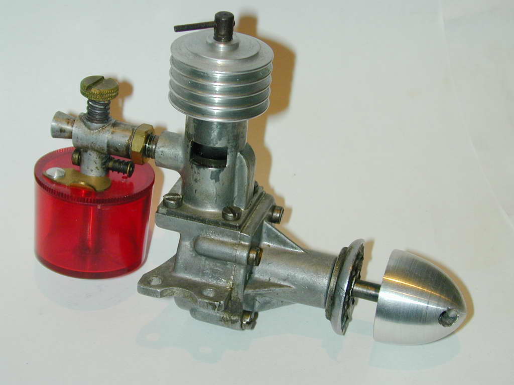
- Type 4 is the relatively common roller bearing type and was introduced by December 1948. It still had the all metal tank, although some later examples have the brass tank support mounting plate strengthened by the inclusion of two pressed in flutes running fore and aft. Still later examples had the red plastic tank as fitted to the Comp Special, although this was no good for use with glow fuel. Examples are: 3N 10/8 produced Dec 1948, 3N 394/8 produced Dec 1948, 3C 76/9, 3D 211/9, 3E 161/9 (red tank), 3J 133/9, and 3K 55/9 (red tank).
- Type 5 is the ultra rare sideport Mk III, really just a bigger bore version of the Comp Special but built on the Mark III crankcase and using a diecast front housing with ED and Mk III cast on the top and bottom faces of the housing as you look from the front. This is evidence that ED intended to produce the sideport Mk III as a serious production engine although it was never advertised. The front housing appeared on Comp Specials with the last I of the III logo neatly ground off, although occasionally ED were lazy and forgot to do this which accounts for the odd Comp Special appearing on eBay as a Mark III! It appears that the sideport Mk III was only available from the factory to special order and no boxed example examples have been seen. Production numbers, from mid to late 1949 through 1950, for this were very low and were probably numbered in sequence with ordinary Mk III's. Examples serial numbers are 3D 158/9, 3J 10/9, and 3K 69/50
- Type 6 is even rarer: a ballrace version of the Mk III side-port. Only one example of this engine is know to exist and currently resides in Kevin Richards' enormous ED collection with the serial number 3G 11/50. It is actually impossible to tell from an external examination that this engine is ballraced, but inspection removes all doubt. The crankshaft appears to be a Comp Special type (crankweb counterbalance cut-outs and square prop driver section). Taken together, they may indicate a factory experiment at performance improvement.


Then there are examples which don't quite fit in the taxonomy. For example, D3 397/8 which should not have scallops in the head, but does, and 3N 233/8 which should have a roller bearing crank, but doesn't! The former could be explained as a replacement part, although there is no evidence of this. The latter engine is from an "N" for overflow batch. ED may have run out of bearings but still wanted to produce product for the Christmas rush, so quietly made some without. We'll never know.


The review by Lawrence Sparey, which was rather belatedly published in the April 1949 issue of Aeromodeller magazine, gives constructional details of the Mk III. While his text describes the Type 4 roller-bearing engine, the excellent cut-away drawing shows a Type 2 plain bearing engine with the scalloped head, as does the 3-view line drawing. The underlying design of the Mk III was clearly based on the existing Mk II and Comp Special designs. It has the same stroke of 0.625 inches, the extra displacement being obtained by increasing the bore from 0.50 inches to 0.55 inches. The same "stovepipe" cylinder design with twin large-sized exhaust ports, soldered-on brass transfer passage, a deflector "step" milled into the piston crown and screw-on cooling jacket was used. The carburettor boss for the sideport induction system was naturally omitted on Types 1 to 4. Full advantage was taken of the fact that the casting for the Mk II case could be used almost unaltered for the Mk III given that both shared the same the stroke. However the extra bore required a change in the PCD (pitch circle diameter) of the cylinder mounting screws, so the two are not interchangable.
The turned hardened steel rod of the 2cc models was retained, albeit with a larger rod diameter and a larger gudgeon pin diameter to accommodate the increased loading. The shaft however was completely different, having a far greater journal diameter to accommodate the passages for the crankshaft rotary valve system which was utilized in place of the earlier sideport system. Unlike the bearings used in the Mk II and Comp Special, which had cast-iron bushings, the shaft of the Mk III ran for the most part directly in the alloy of the front casting. This was forced upon the makers by their use of a larger-diameter shaft running in the same basic housing—no room for the bushing!

The engine attracted considerable notice among competition modellers right from the start of its production career. A major factor which inspired this attention was its use of a crankshaft rotary valve for the induction system—as far as I know it was the first British production two and a half cc diesel to use such a system. In addition, it pioneered the use of a roller bearing at the rear of the crankshaft (of which more later). To a competition modeller, these must have appeared as significant recommendations for the design.

A further significant attraction was the fact that the use of the same case and mount holes meant that the Mk III could be bolted straight into a model that had originally been built for the Comp Special. It’s true that it would be necessary to remove the tank for this to work, but most aeromodellers likely didn’t use the tank anyway—far too bulky for free flight and not the right type for control line. This probably explains why so many of these engines turn up without tanks. With their tanks removed (as would normally be the case in control-line service), the Mk III and the Comp Special weighed in at 170 gm (6.0 ounces) and 156 gm (5.5 ounces) respectively, so for a weight penalty of only half an ounce, the modeller could get a bit more power. Frog were to repeat this approach with their 160 glow and 180 diesel models, which had the same mounting set-up as the 100 Mk II. Influences!

The crankshaft rotary valve used in this motor is well worthy of comment. The induction port in the large-diameter crankshaft was milled tangentially around a portion of the circumference of the journal, resulting in a port which was quite narrow in an axial direction but quite long in a circumferential direction. This port was more like a round-ended circumferential slot than a hole, and the round ends of the slot were doubtless most effective in limiting the development of stress concentrations at this always-vulnerable location. The axial width of the port matched the fairly small-diameter induction tube in the main bearing casting, so that it offered no constriction whatsoever when fully open. In addition, the fact that it was cut into a fairly large diameter shaft meant that it gave rapid opening and closing of the induction system—more like a disc valve than a conventional shaft rotary valve of the period. Coupled with the use of a surface needle valve set-up which offered minimal restriction in the venturi-section choke tube, this was an extremely efficient rotary valve design. It fed a crankshaft passage of generous diameter, and the net result was a very efficient induction system, especially by the standards of the day.
Another selling point was the use of an extended prop driver which placed the prop well forward of the cylinder and made cowling (then very fashionable) relatively straightforward. ED were to continue this concept with their later Mk IV 3.46 models and Amco also followed suit with their 3.5 plain bearing model. Influences again...

The needle valve control supplied with the engine featured a brass thimble which was fitted with an internal tensioning spring, like that used on the ED Bee. Sparey reported that this spring alone was ineffective in terms of preventing needle valve creep when the engine was running and later examples used a split in the thimble for tensioning, although the internal spring was retained. The spraybar was a complex affair, larger in diameter than the venturi opening with a separate right-angle fuel nipple soldered on and another tube forming a fuel jet pressed in from the needle valve spring opening side. The tip of the jet is just visible in the venturi opening of this photo, although the location in relation to the opening is somewhat variable. The supply side was fitted with a friction-fit cut-out arm that admitted air when opened, eventually shutting down the engine. Sparey always reported these as being less than highly effective at high revolutions.


There was a spigot on the outer end of the needle valve thimble onto which a spring was wound, with a needle valve control extension at the other end of the spring. This needle valve extension, while provided with all engines, is often missing on examples of this engine which are encountered today. LNIB example have been inspected that show no sign of this extension and the one tested by Sparey also lacked the extension. Either users removed it, lost it, it fell off, or it got wiped out.

The engine was also supplied with a glow-plug conversion kit which featured an aluminium button to replace the contra-piston. The plug screwed into this button, and the button and plug were secured in place by an alternative cooling jacket which was machined away on the centre to clear the plug. Amco were to offer an almost identical conversion kit for their 1949 3.5 plain bearing model. Influences yet again!

The diesel and glow cooling jackets were provided with six indentations in the outer edge of the top fin to facilitate removal and tightening of the jacket. A very neat and effective wrench designed to fit these indentations was supplied with each engine to facilitate the changing of the alternative heads as well as the tightening of a loose cooling jacket if necessary. It’s a puzzle why they didn’t machine the six indentations into the Comp Special head and provide a similar wrench with that model too. Cost, one supposes.
As of early 1948, engines were packaged with a generic instruction manual covering all three of the then-current "stovepipe" models. This manual was far more detailed and hence far more useful than those supplied with many other contemporary engines. Altogether, a very comprehensive package indeed and a credit to the ED company. Price in 1949 was £4 5s 0d. Very reasonable by the standards of the day for what you got in terms of performance and accessories.
 |
 |
 |
 |
There seems to be little doubt that for a time at least the Mk III was the most powerful British production diesel of its size. Following its introduction, the engine enjoyed a period of considerable competition success, both in aircraft and model cars. However, model engine design was in a rapid development phase during this period, and the performance edge enjoyed by the Mk III was not to last long. By late 1949 it was being seriously challenged by a number of other designs from other makers, notably Aerol Engineering with their Elfin range. ED met this challange with the highly popular "ED Mk III Series 2", introduced in about June 1951. As mentioned earlier, this engine is better known as the 2.46 Racer.

The roller bearing used in the Mk III featured 17 hardened and ground steel rollers running in a steel outer race which was press-fit into a recess machined in the front bearing housing. While a standard ball-race does little to assist with axial thrust loads, a roller bearing does absolutely nothing. To make some pretence at accommodating axial loads, the hardened steel outer race of the rollers protruded into the case a little way. The thrust-face of the crankweb was increased in diameter to bear against this protrusion, thus transferring the thrust loadings from the shaft to the case and providing a tiny fore-aft float for the rollers.
 From the previous photo, it would appear that ED made two types of crankshaft for the Mk III, but they were more economical than that. The larger thrust-face is actually a hardened washer, relieved on the rear side to sit over the standard shaft thrust-face. The fit is so close that given time and a bit of gunk, the two can look like a single unit, but there are two give-aways. First is the sharp transition between shaft and thrust washer; a highly stressed point like this must have a radius, as ED certainly knew. The other give-away is the hole in the crankpin. With the washer in place, it would appear blind, making it useless for jigging. This shot shows the washer prised away from the shaft.
So we have a large diameter and hence high velocity hard metal on metal thrust bearing, followed by a roller bearing under high, intermitant radial load in one direction only, followed by a metal in unbushed aluminium contact area. A complex arrangement to manufacture and not all that mechanically efficient.

The rollers were completely un-caged, nor were they provided with any form of spacers as in the case of the far later Rivers design. Hence there was nothing preventing them from skewing or rubbing against one another, should they feel so inclined. They are assembled sufficiently loosely that rubbing friction between rollers should not be a major problem unless skidding or minute variations in their relative diameters were to cause bunching. But for this bearing to work effectively, an extremely high level of precision (at a commensurately high cost) would have been required, since essentially no radial play could be tolerated in this bearing if shaft support was to be maintained. This would require hyper-accurate fitting of the shaft journal, rollers and outer race as well as the use of suitably hardened wear-resistant materials.
The plain bearing version of the front housing was provided with some interesting arrangements to optimize lubrication. The integral thrust bearing shoulder was interrupted at two opposite locations (top and bottom) to allow lubricant access. In addition, two channels led away from these cut-outs into the bearing itself, tapering off in width and depth as they progressed along the bearing. The one on the top surface stopped just short of the induction tube (as it had to do to maintain primary compression) and the lower one stopped at the same point opposite. Most interestingly, there was a similar tapering channel cut beyond the induction tube to supply oil to the front of the bearing.
 The roller bearing model has a very tricky, long, inclined oil passage drilled from the bottom of the inner face of the casting to intersect the plain bushing area (visible in this photo after you know where to look). Overall, the roller bearing design is not what I would consider particularly well thought out. In fact, I can see it being quite costly to produce and can also envision a certain amount of operational trouble arising from the use of this bearing as time went on. If it failed or wore out, the shaft would be effectively unsupported at its most highly stressed end and would become subject to a substantial cyclic bending load due to the rollers no longer doing their job as shaft supports. And it was certainly a power robber in terms of its function as a thrust bearing, probably offsetting any frictional reductions arising from the use of the roller bearing to accept radial loads. Really, I can’t see how it and the associated oil passage for the plain bearing section justified the cost and complexity of its inclusion.
A word of caution to owners of these engines: be extremely careful when dismantling the shaft assembly! Really, the roller bearing version is best left undisturbed. First check to see if you have a roller bearing or a plain bearing assembly – the differences are obvious from an examination with the shaft still in place. If you really must dismantle a roller bearing version, you need to be aware that there’s nothing restraining the rollers when you remove the shaft from the bearing, and hence they are free to spill out all over! And they’re very small—once lost, lost for good! Take precautions!
The technique is to apply some thick oil to the set-up (gear oil is good) and to push the shaft upwards very slowly in a vertical direction with the web uppermost. If you do this carefully, the rollers will remain in place in their outer race. But great care is still required, since it’s only the surface tension of the oil that holds them in place once the shaft is out. I have always used a large biscuit tin as a catch basin when dismantling these shaft assemblies, and it has saved me several times from losing rollers. Naturally, if you have the plain bearing version, these precautions become unnecessary. To re-assemble the bearing if the rollers have been removed for cleaning, etc, it’s best to smear grease into the outer race and then insert the rollers one at a time. The grease holds them in place until the shaft is re-inserted. Again, do this over a secure catch basin!

The engine was supplied with a very large tank that hung under a brass mounting plate secured to the engine by the rear cylinder mounting screws. This tank could only be used with the engine in an upright position and due to the central fuel pick-up point, was essentially useless for control-line flying. It was also far too large for free-flight, though would have been fine for bench running as well as for model car use (then very popular). Sparey reported that the brass mounting plate fractured during his tests due to the cyclic stresses arising from the vibration of the tank set-up when the engine was running. On later engines, flutes were pressed into the mount for some added strength. Some, but by no means all Mk III's have the required number of turns to open the needle stamped onto the boss that provides the fuel pickup and screws the tank and its attachment bracket together. A nice touch, provided the original spraybar and needle remain with the engine, and the fuel mixture used remains close to whatever ED recommended for the engine.
 Another point worth noting—one quite often sees these engines assembled with the transfer port at the rear of the cylinder. This is incorrect! The transfer should definitely be at the front. Sparey’s published view and that in the ED instruction manual both confirm this and there’s good reason for this location. If you examine the layout, you’ll see that locating the transfer at the rear results in its lower entry point being almost completely obscured by the piston and the case surface at and near bdc. Not good for efficient transfer and scavenging! When located at the front, the port entry remains relatively unobstructed. Naturally, the deflector step in the piston crown and the transfer have to be in alignment.
 The obstruction issue also explains why you find so many ED Comp Specials and the odd Mk III with an additional "step" or cut-away filed or milled into the lower skirt of the piston directly below the deflector cut-away in the crown. The idea was to eliminate the tendency of the descending skirt to obstruct gas entry into the transfer port. This was a standard performance modification to Comp Specials and Mk III’s on the part of those who wanted them to give their best; Peter Cock’s 1948 Gold Trophy winning Comp Special (in his famous Kan Doo) was modified in this way by Peter’s own account. In fact, the effectiveness of this simple modification leads one to wonder why ED didn’t include such a cut-away as a standard feature. Cost, presumably. My trusty old "flyer" Comp Special is modified in this way, and it’s 500 rpm up on my best unmodified example in the 7,000-8,000 rpm range at which the engine was intended to operate. My recent Mk III acquisition has also been neatly modified in this way by some knowledgeable previous owner.

This page designed to look best when using anything but IE!
Please submit all questions and comments to
enquiries@modelenginenews.org
|
Unless otherwise expressed, all original text, drawings, and photographs created by
Ronald A Chernich appearing on the Model Engine News web site are licensed under a Creative Commons Attribution-Noncommercial-Share Alike 3.0 License. |

|