The One That Got Away:
The OS Max-D 15 Diesel
by Adrian Duncan
 |
 |
 |
 |
| Click on images to view larger picture. | |||
This time we look at an engine that is seldom encountered today and hence has been more or less consigned to the status of legend when it is remembered at all. We're talking about the O.S. Max-D 15 diesel, a fine design in its own right but one which appeared at a time when its chances of success were severely limited by the surrounding circumstances. As a result, the engine did not remain long in production and relatively few were made, especially by O.S. standards.
Even among those who remember this engine, its characteristics are frequently misunderstood. It has commonly been thought of as simply a twin ball-race diesel conversion of the then-current O.S. Max .15 glow model. This is very far from being the case, as we shall see.
But first, in order to understand how this engine came to exist at all it is necessary to delve into the history of the O.S. enterprise and its relationship with its commercial rivals, particularly Enya. So here goes
Introduction
It's astonishing how few of today's modellers seem to be aware of the fact that the familiar O.S. trade-name enjoys a unique distinction which is unlikely ever to be taken over by any other—it has been continuously associated with the model engine trade for the longest period of time of any trade-name in model engine history. With each passing year, this respected Japanese company's record of ongoing involvement in model engine production grows another year longer, and it seems doubtful that any other maker will ever surpass the production record of O.S., now almost midway through its second half-century and still going strong. You have to be at least 72 years old as of the time of writing (2008) to have lived at a time when O.S. model engines were not being manufactured! Thankfully, I don't qualify!
The O.S. company (officially the Ogawa Model Manufacturing Co. Ltd.—O.S. is merely a trade-name) was founded between the two World Wars by Shigeo Ogawa of Osaka. During his formative years, Mr. Ogawa was a very keen modeller who was greatly attracted to the field of model engineering. In 1936, while still in his teens, he somehow scraped together enough money to buy a lathe and drill press, and with this very basic equipment he began making model steam engines and live steam locomotives, an interest which he was to maintain throughout his working life. He quickly became a skilled machinist.
In that same year of 1936, Mr. Ogawa made his first model internal combustion engine, a .10 cu. in. side-port spark ignition job which he initially installed in a model boat. This of course made him one of the original Motor Boys! The little engine performed so well that other Japanese modellers who saw it were quite impressed and asked him to make copies for their use also. Accordingly, a few more examples of this engine were made and distributed to a small circle of Japanese modellers during 1936. The majority of these were put to model aircraft use.
Ogawa-san's initial efforts drew sufficient attention from his fellow Japanese modellers that in 1937 he was encouraged to commence small-scale commercial production of the first of what was to become a long line of O.S. engines. The company trade-name arises from the fact that in the Japanese language the family name is always placed before the personal name—hence, the letters O.S. are simply Ogawa-san's initials placed in their Japanese order.
The first O.S. design to be put into commercial series production was the neat little .10 cu. in. displacement model which had been Mr. Ogawa's initial effort in 1936. Production of this model was initially restricted to around 20 units per month—a very far cry from the scale of things to come! However, the continuing positive reception of this engine soon encouraged Mr. Ogawa to expand his fledgling range beginning later in 1937, and by 1941 he had designed and put into limited production a series of spark-ignition engines covering no less than six additional displacement categories from .27 cu. in. up to .58 cu. in. These included an impressive three-cylinder unit intended for marine use. He even succeeded in getting a few of his engines sold in the USA, no small feat for a fledgling Japanese manufacturer at that time. The Ogawa enterprise was well on its way!!
However, at this point WW2 intervened, and that unhappy event naturally put the brakes on Mr. Ogawa's model engine development activities—international trade opportunities ceased immediately and in any case his production capabilities were needed for other purposes. He did manage to produce a couple of 9.43 cc models in small quantities for the domestic market (such as it was) during 1942 and 1943, but at that point the tide of the war dictated the complete dedication of his talents to war production. Accordingly, it was not until after the end of that conflict that he was able to resume commercial model engine manufacture.
The conclusion of the war found large numbers of American servicemen stationed in Japan with the occupation forces. This created a sizeable market constituency with discretionary spending power far in excess of that of the average Japanese citizen in the immediate post-war economy. A proportion of these service personnel were of course modellers in their spare time, and there was an obvious market niche to be filled in supplying their need for model engines and related products.
Taking full advantage of this opportunity, Mr. Ogawa lost no time in re-establishing his factory in Osaka on a larger scale and was back in full production by 1946 with a 9.7 cc crankshaft rotary valve model. This was further refined with an updated 9.3 cc model later in the same year, followed by a revised 9.85 cc design in 1947. Spark ignition was naturally retained in all of these models It was also in 1947 that the first of several O.S. model pulse jet engines appeared in commercial form.
Beginning in 1948, Mr. Ogawa attracted a good deal of attention with his ball-bearing disc valve .64 cu. in. racing motor, which was the first O.S. engine to be offered in glow-plug configuration, although a spark ignition version was also available. It appears to have been the success of this design which inspired the Tokyo-based Enya brothers to develop their own broadly similar .63 cu. in. racing model which finally entered production in late 1949 and was quickly joined by several other Enya models. By then, Mr Ogawa had designed his famous 1949 twin-stack .29 cu. in. glow-plug model, and it was the 1950 "New 29" version of this engine which finally put O.S. on the international modelling map. Mr. Ogawa was successful in reaching an agreement with Bill Atwood to distribute this model within the United States, and production soon reached 1000 units per month.
The range continued to expand as the 1950's went on, with a healthy rivalry developing between the Osaka-based O.S. company and the Enya Metal Products Co. of Tokyo as both companies expanded their marketing efforts world-wide. O.S. achieved a major publicity coup in 1956 when their powerful and light 1955 Max-I 15 glow model powered Britain's Ron Draper to the 1956 Free Flight World Championship.
Enya fought back in late 1956 with an improved version of their own 1955 15-I glow model, the excellent Enya 15-IB (originally designated the 15-IS). They also produced a limited number of high-performance "specials" based on the 15-IS and 15-IB. This evened the performance score for a time, but O.S. were always quick to respond to any challenge from Enya and soon countered vigorously with an updated version of their established 15 model, the even more powerful and ultra-lightweight 1958 O.S. Max-II 15.
However, Enya had in the meantime achieved a master stroke of their own, to which O.S. had no immediate reply—in late 1956 Enya had introduced the first model of their deservedly famous 2.5 cc (.15 cu. in.) diesel, the D15-I. This highly innovative design featured a then-unique system of loop scavenging with a baffle-less piston and directional porting which actually incorporated some elements of the Schnuerle porting system that was soon to dominate the field of high-performance two-stroke engines, both model and full-size. The quality, design and performance of the Enya D15-I turned a lot of heads, particularly in Europe where diesels were still the dominant type of model engine, at least in the displacement categories up to 3.5 cc (.21 cu. in.).

Naturally, O.S. felt that they couldn't take this lying down, and during 1957 they embarked upon a development program of their own with the intention of producing a .15 cu. in. diesel that would beat anything that their Enya rivals could produce. The result was the main subject of this essay—a forgotten classic, the O.S. Max-D 15.
Genesis of a design
Prior to 1957, the O.S. company had shown little interest in diesels. It is true that they had briefly produced a 1 cc (.06 cu. in.) sport/beginner's model in the period 1949-50, but this was an unashamed copy of the English ED Mk. I Series I Bee and showed little or nothing in the way of original design thinking. It did not remain in production for very long, and O.S. went back to doing what they did best—producing high-performance glow models to very high manufacturing standards. The 1 cc diesel actually made so little impression upon their corporate consciousness that it was omitted from their famous 40th anniversary summary sheet which claimed to show all of the models that they had produced as of 1976! It took the march stolen on them by Enya with the D15-I to re-awaken their interest in becoming involved once more in the field of model diesels.
In doing so, it's clear that O.S. wanted to meet Enya head-on and attempt to beat them at their own game. So a conventional or derivative design would not do at all—any O.S. diesel model had to possess at least as much technical interest and innovation as its Enya rival. It also had to look and feel like an O.S. original—merely putting the O.S. name on a derivative design copied from elsewhere would not serve the purpose!
Now in one respect, Enya had gone way out on a limb with their D15-I model—they had completely abandoned almost every design feature of their basic 15 glow model and had started afresh with a clean sheet of paper. As a result, the only common element of both the Enya 15 glow and diesel models was the needle valve assembly!

By contrast, O.S. elected to stand firmly upon ground already gained with their glow models and draw as far as possible upon their previous experience in producing high performance .15 cu. in. glow engines. In their evolving Max-II 15 glow model they had an excellent basic design upon which to draw—the only question was to what extent the design features of this fine glow engine could be effectively transferred to a diesel model. O.S. set out energetically to seek some answers...
At the time in question, it was commonly held as a truism that it was not practicable to design a variable-compression model diesel engine which used loop-scavenging in conjunction with a conventional piston having an upstanding baffle. This was the standard design of the period as far as medium and large-displacement glow engines went, but such engines used a fixed cylinder head which could be contoured to accommodate the baffle on top of the piston and was retained in the correct orientation at all times by the head screws.
It was true that the early French Morin 5 cc diesel had used a baffle piston, but that was a fixed compression design in which the head was easily contoured to the piston and held securely in place. The fact that a variable-compression diesel used a contra-piston which was generally a simple iron or steel slug with nothing restraining any tendency towards rotational creeping in the bore during operation seemed to most people to dictate the abandonment of any ideas about using a baffle piston. Enya certainly thought that way—their D15 model used a conventional "diesel" piston with a simple conical crown and a matching contour on the contra-piston underside. MVVS more or less copied the Enya design wholesale with their own 1958 loop-scavenged diesel design, and Frog were to adopt a similar approach with their fine loop-scavenged 3.49 cc (.21 cu. in.) diesel of 1959.
O.S. were clearly unimpressed by such considerations. Their view was that if the loop scavenging set-up with a baffle piston worked well for glow engines, there was no reason why it shouldn't work equally well for a diesel. In their minds, the only challenge involved was how to deal with the need to create a contra-piston that could be contoured to accommodate the piston baffle and then restrained against rotation in the bore so that the contouring of the contra piston remained in alignment with the piston baffle. In other words, O.S. were quite prepared to accept the challenges attached to the use of their established and very successful gas flow arrangements in a diesel model and to solve the attendant design problems by thinking "outside the box".
The great attraction of this approach was the fact that if such a system could be made to work then much of the already-completed and highly effective development work on the gas flow arrangements for the company's existing .15 glow model could be transferred directly to the new diesel model. Plus this would give O.S. a technological "first" to match that achieved by their rivals at Enya—the world's first loop-scavenged variable-compression diesel with a baffle piston. This then was the approach that they elected to pursue.
Apart from their brief flirtation with a ball-race crankshaft in their 1948 .64 cu. in. racing model mentioned earlier, O.S. had hitherto stuck to the production of engines with plain bearings. The new diesel model was intended to fly the O.S. colors high in the performance sweepstakes, and so the decision was taken that the shaft of the new model would be carried in twin ball bearings. It was in fact only the second O.S. design to do so.

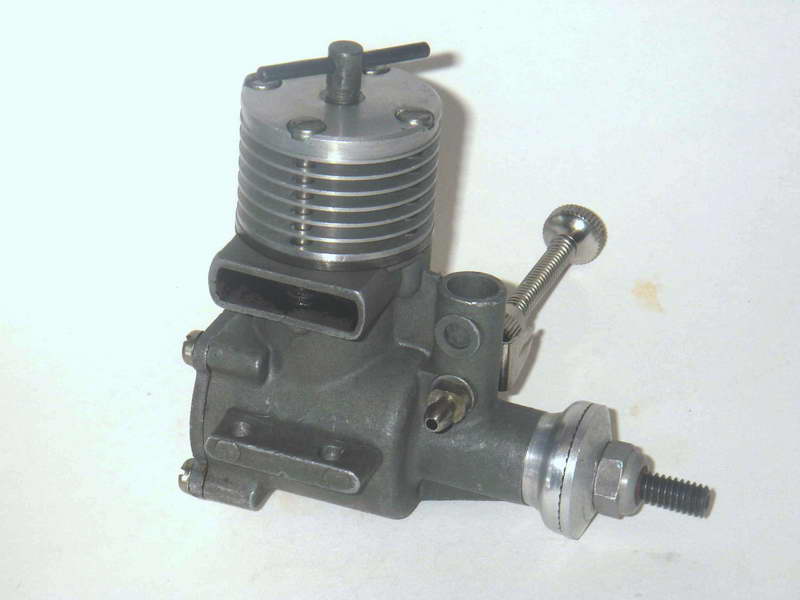
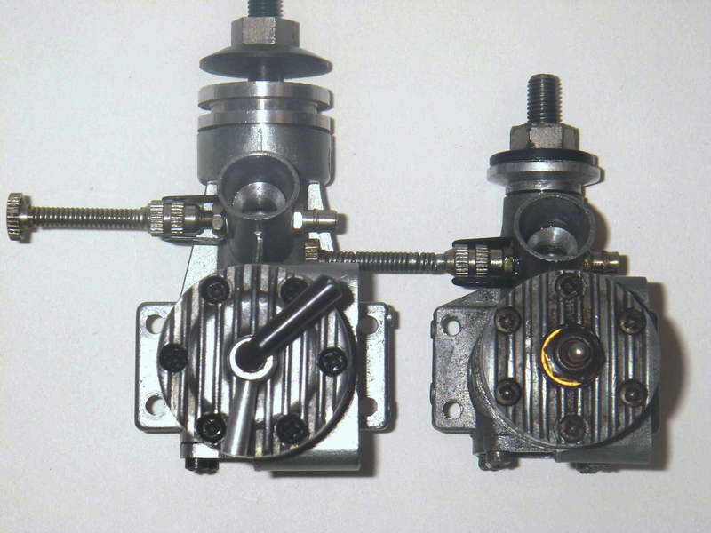
Apart from this, the family resemblance of the O.S. Max-D 15 to its glow sibling, the Max-II 15, is very obvious. The diesel is considerably bulkier and heavier due to the extra height imposed by the diesel cylinder head arrangements, the need to strengthen the engine to deal with the increased stresses arising from diesel operation and the use of a twin ball-bearing shaft. But unlike its Enya rival, the Max-D 15 bears a strong visual similarity to its glow cousin and is easily recognizable as a "standard" O.S. design through and through, just as O.S. clearly intended it to be.
How was this achieved?? Let's take a look inside my own LNIB example of this rather rare engine and see...
The O.S. Max-D 15—description

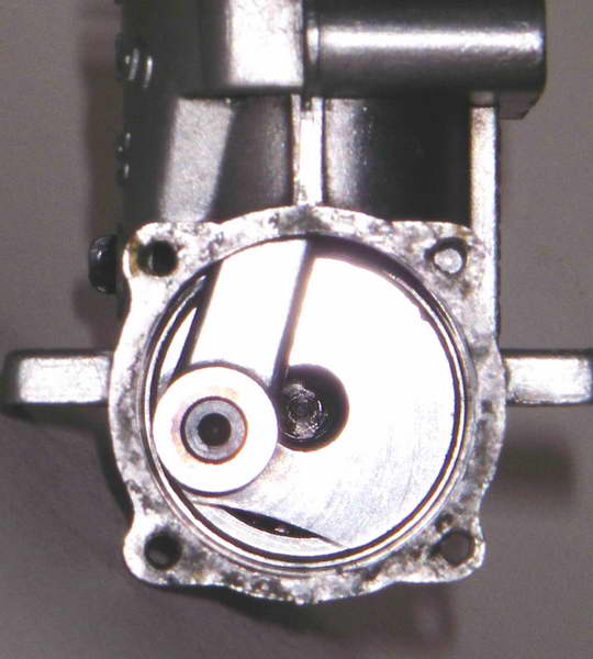
In describing the Max-D 15, I was only prepared to go so far in terms of dismantling this rather pristine example—I didn't want to damage the original gaskets, for example. This was no issue as far as the cylinder head went, because the fact that this is a diesel meant that there is no gasket up there! The backplate came away easily too—the gasket was not bonded either to the case or the backplate flange. But the cylinder was well and truly bonded to its base gasket, and I was not prepared to disturb it and risk damaging the seal. So the details of the cylinder and the crankshaft assembly will be best appreciated by examining the attached exploded drawing supplied with the parts list for the engine. It shows all the major details quite clearly.
The changes required to transmute the basic design of the O.S. Max-II 15 glow engine into a diesel model can be divided into two distinct categories—those required to strengthen the engine from a structural standpoint as well as accommodate the ball-bearing crankshaft; and those required to convert the ignition system from glow to diesel. Let's look at the latter challenge first.
The decision was taken early on to stick with the same kind of baffle piston as that used on the Max-II 15 glow model. Consequently, the piston used in the Max-D 15 is essentially identical in overall form to that used in the Max-II 15—it is a completely conventional but very light cast iron baffle-topped unit which is lapped to a truly superb fit in the hardened steel cylinder. It has two skirt ports below the crown on the transfer side which align at bottom dead centre with two corresponding ports drilled through the cylinder wall below the transfer port. This is clearly intended to facilitate the passage of gas through the bypass to the transfer port itself as well as to promote improved piston cooling.
The cylinder porting too is essentially identical to that of the glow model. The real trickery is to be found up at the top of the cylinder. Three requirements had to be met here. First, enough room had to be created for the contra-piston and its operating mechanism, preferably without making the engine too tall in the process. Secondly, the presence of the baffle on the piston crown had to be accommodated in a manner which did not result in an overly inefficient combustion chamber configuration. And thirdly, the accommodation of the baffle had to be maintained at all times regardless of the compression setting and of any tendency for the contra-piston to creep out of its correct alignment in the bore.

The first issue, that of creating enough room for the compression adjustment system, was quite simply accomplished by making a revised cylinder which had a considerable length of additional bore added above the region of top dead centre. The diesel cylinder actually has an extra cooling fin above the exhaust level, and there is an unfinned additional length of bore which extends above the finned section like a spigot. The cylinder head fits over this spigot—a clever arrangement because it means that the lapped contra-piston operates for the most part inside the head rather than below it. In this way, the additional extra overall height of the unit is minimized. Despite this, the engine is considerably taller than its glow counterpart as well as being quite a bit longer.
The second of the above requirements—the need to accommodate the piston baffle—was met quite simply by milling a slot into the underside of the contra-piston which accommodated the baffle on top of the working piston. But the designer did not stop there with merely achieving the required clearance. Apart from being made oversize to allow adequate clearance, this slot is actually somewhat bevelled towards the exhaust side so that the baffle does not by any means fill it at top dead centre. As the piston nears top dead centre, an ever-greater proportion of the remaining space above the piston is represented by the slot around the baffle and the gas above the piston will increasingly be forced by displacement to concentrate in that area. This will have the effect of causing mixture to move rapidly in from the cylinder side walls towards the area around the baffle as the piston nears top dead centre. The baffle slot thus performs much the same function as the squish bowl in a model glow motor cylinder head by concentrating the charge and promoting swirl within the combustion chamber. This should result in higher combustion efficiency once ignition has been initiated. The principle had of course long been applied to glow engines, but this was the first example of its use in a commercial model diesel.

OK, so much for accommodating the baffle; now, how to ensure that once the engine is assembled, things remain in line? Quite simple, really—the designer cut a notch into the upper wall of the contra piston on the exhaust side (opposite the cut-away for the baffle) and cast a corresponding key into the underside of the aluminium alloy cylinder head.
 Assembly is slightly complicated by the fact that the contra piston has to be installed in the correct alignment to begin with, but an installation error (and potential damage to the engine when turned over) is precluded by the fact that if the contra piston is not installed in correct alignment the cylinder head simply will not fit! And once the head is installed with the notch correctly aligned with the key, there's no way that the contra piston can get out of alignment by rotational creeping in the bore. Very simple, and very effective! So much for not being able to make variable compression loop-scavenged diesels with baffle pistons!!
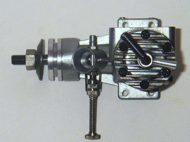
The top of the engine is completed by a perfectly conventional single-arm compression screw. This is fitted with an extremely neat and effective compression locking lever. The contra-piston is a relatively slack fit in the bore by normal diesel standards, so this locking lever appears to be a necessary feature.
OK, so there we are with a very practical top end setup for our new world-beating diesel! Now, how about the matter of dealing with the additional stresses imposed upon the working parts by diesel operation? The mechanical loadings encountered in a diesel are inevitably considerably greater than those generated in a glow model of similar displacement and design. To deal with this factor, a number of steps were taken.
Firstly, in order to accommodate the radial stresses imposed by the lapped contra-piston, the cylinder walls were very sensibly made significantly thicker than those on the glow model. This extra thickness was carried the full way down to the locating spigot at the base, resulting in a very sturdy and dimensionally-stable cylinder overall. To maintain cooling fin depth, the outside diameter of the cylinder fins was made larger as well, and consequently the cylinder of the diesel model is substantially bulkier and heavier than that of its glow relative.

This in turn led to a requirement to increase the size of the crankcase casting to accommodate the larger cylinder base. While they were about this, the designers also took the opportunity to increase the wall thickness of the crankcase. Hence, the revised crankcase was significantly bulkier and far sturdier than that of the glow model, and the extra size was also useful in accommodating the ball bearing shaft. The diesel case was tumbled to a fine satin finish, unlike that of the Max-II 15 which was sand-blasted to a matte finish.
A possibly negative but inevitable consequence of the modified crankcase was the fact that the mounting between the diesel and glow models was not interchangeable. The lateral spacing of the diesel mount holes is considerably greater than that of the glow model, as is the required bearer spacing.
A revised con-rod was used in the Max-D 15 which is substantially more sturdy than its glow counterpart. The big end is bronze-bushed for good wearing qualities. Although I couldn't measure it directly, the gudgeon pin of the diesel appears to be of larger diameter than that of the Max-II 15 glow model. This means that although the pistons of the two models are generally very similar, that of the diesel model is modified to accommodate the larger gudgeon pin and hence is not interchangeable.
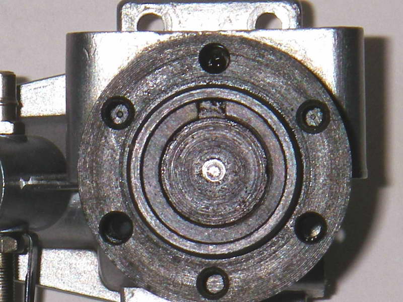
The rest was perfectly conventional model engineering design—the re-configured crankcase accommodated the twin ball bearings and a revised crankshaft was developed to fit those bearings and provide adequate strength. The revised crankcase die naturally incorporated the Max-D15 designation plus the possibly redundant information that this was a diesel! The latter information appeared on a vertical rib cast into the right side of the new crankcase below the exhaust stack, presumably for added strength below the location of one of the three main cylinder hold-down bolts. The glow model only used two such bolts, but the designers clearly felt that the diesel required the extra bolt.
The very sturdy crankshaft is perfectly conventional, stepping down in diameter at the rear of the front ball race in the usual manner. I was not able to measure the diameter of the shaft directly, but by scaling it off the parts list drawing the rear journal appears have a diameter of 10 mm, stepping down to 7.5 mm behind the front ball race. These are of course very sturdy dimensions for a 2.5 cc diesel. A healthy degree of counterbalance is built into the crankweb. The internal gas passage is drilled to a reasonably generous 0.250 in. (6.35 mm), leaving ample wall thickness for strength.

The shaft features the usual O.S. rectangular induction port which is used in conjunction with a generous 9 mm dia. induction tube, giving very rapid opening and closing. Obviously the engine would never work on suction with such a large venturi, and the engine as supplied was fitted with a turned alloy insert to bring the throat diameter down to a far more rational 5.5 mm. This could of course be drilled out, although a larger sized insert was available as an optional extra, allowing some fine-tuning of the induction system. An R/C throttle was also available for this engine—a clear precursor of the coming dominance of R/C engines in the marketplace.
The prop driver is locked to the shaft by means of a tapered split collar in the usual manner. Oddly enough considering the engine's Japanese origin, the thread used for the prop-nut is a very non-metric 12-36! The needle valve assembly is the same as that used on the contemporary O.S. Max 15-II glow model.
The result is a very handsome engine of obvious O.S. heritage, looking exactly like what it is—a .15 cu. in. diesel broadly based upon the design of the Max-II 15 but with the addition of twin ball-races and compression ignition. It retains the glow model's bore and stroke of 15.19 mm and 13.70 mm respectively for an identical displacement of 2.48 cc. However, the diesel model weighs in at a healthy albeit not unmanageable 6.2 ounces (177 gm)—a lot more than its 3.5 oz. (100 gm) glow stablemate and also well in excess of its 5.1 oz. ( 145 gm) Enya D15 rival! It's also far more bulky overall. But the extra weight and mass have been put to good use—the engine seems very sturdy, and should be good for a long and trouble-free working life.
At this point, it's worth noting in passing that in two respects Enya had the last laugh! The first of these was the fact that the modifications that O.S. were forced to make to their basic glow model to produce the Max-D 15 were sufficient in number that, like its Enya counterpart, the Max-D 15 ended up sharing very few components with its glow stablemate! The two models used the same needle valve assembly and prop-nut, but that was it—everything else is different!! So although they didn't throw away the standard design blueprint, O.S. ended up being forced to follow Enya's lead by making an entirely new engine as opposed to a modified version of their existing glow model. That said, the Max-D 15 is recognizably a standard O.S. design, just as it was clearly intended to be.
The other area in which Enya could afford to feel that they had "won" was the fact that their .15 cu. in. diesel series achieved far greater popularity than its O.S. rival and hence remained in production for a considerable period of time—long after the demise of the Max-D 15, in fact.
Performance

OK, so now we know what it looks like and how it is configured internally. Next question—how does it run?? Here we are on slightly shaky ground, because I have chosen not to run this LNIB example so that it's present condition can be maintained. I did have another less pristine example many years ago, and that one did get a bit of running, although I never flew it. So we'll have to depend upon my notes taken all those years ago.
Fortunately, the said notes are fairly detailed. They record one characteristic that the Max-D 15 shares with its Enya counterpart, namely the need for a slightly unusual approach to starting by diesel standards. Like the Enya, it is extremely reluctant to start or even fire unless quite heavily primed. This would be a considerable disadvantage for team racing, which was one of the uses to which reference was specifically made in the instruction manual. Perhaps things would be better with the engine inverted, as it usually was in a team racer!
However, if you give it a healthy shot of fuel through the exhaust, things soon liven up and a start is quickly and easily obtained. Once running, the exhaust note is rather "odd" while the engine is running rich—it doesn't sound at all like a diesel! A quite "throaty" sound—more like a rich-running glow, really. This is probably a reflection of the porting used. But as you lean it out, things return to normal and it begins to make a more familiar and very powerful noise!
The engine is extremely easy to adjust and runs outstandingly smoothly once properly adjusted. I never took any rpm readings off my former "runner", but I did note for the record that it appeared to be in the upper echelon of 2.5 cc diesels of its period as far as performance went. I noted specifically that it seemed to be faster than my "runner" Enya D15-I—the engine which it was designed to overshadow!
 |
 |
 |
|
| Click on images to view larger picture. | |||
The O.S. factory claimed an output of 0.30 BHP at unspecified rpm for the Max-D 15, which exceeds the measured figure of 0.252 BHP at 14,200 rpm obtained by Ron Warring for the Enya D15-I. Based on my memory plus the fairly detailed comments recorded in my notes, I see no reason whatsoever to doubt the O.S. claim. The standard of manufacture is up to the best that O.S. could produce, which is to say as good as that of any manufacturer anywhere in the world. The engines were supplied with a neat rubber exhaust plug to assist the owner in keeping dust and dirt out of the engine when not in use. A nice touch... all in all, a class package.
The instruction manual was quite comprehensive and written in excellent English. It states that the engine was intended specifically for FAI free flight and team race applications. If this is the case, we may be seeing a clue regarding the engine's apparent failure to make much of an impression upon the market. I would have said that the starting issue noted above would have militated strongly against this engine finding much success as a team race motor, plus I would expect the type of porting used to result in relatively high fuel consumption figures. In addition, I can't see that it offered any power advantage over a good contemporary competition glow engine (many examples of which were on the market by this time) or even a tuned competition diesel such as an Oliver. Furthermore, it weighed substantially more than the glow (and even some of the diesel) competition. These factors would appear to argue against any likelihood of its greatly distinguishing itself in free flight competition.
Perhaps these factors explain why the Max-D 15 appears to have remained in production for a relatively short time. In a sense, it was an engine without a clear purpose. It's difficult to be certain, but all indications are that production had ceased by 1960 at the latest. By contrast, the Enya D15 soldiered on, emerging in a completely revised version in 1960 as the 15D-II, in which form it was to remain in production and in demand for another 5 years. In the battle of the Japanese .15 cu. in. diesels, Enya certainly had the last laugh! They are still producing a range of updated diesels today (2008), including a .15 cu. in. model.
It's unclear how many examples of the Max-D 15 were produced. The serial number of my present example is 1431, and the other example that I owned years ago was numbered 1651. Those are the only two serial numbers that I can report for this model, because these are the only two examples that I've ever seen! So the number ultimately produced is uncertain, but I suspect that it was not large by O.S. standards.
A successor—the O.S. Max-DR15
As noted above, the Max-D 15 appears to have gone out of production by 1960. However, that was not quite the end of the story! In fact, what occurred in 1960 was in effect a reversal of the process under which the Max-D 15 had come into being in the first place!
As of 1960, O.S. had a twin ball-race diesel which had been a technological success but a sales failure. However, there appeared to be no reason why the same basic twin ball-race lower end could not be successfully applied to a competition glow motor!
So the ignition switch of 1958 was reversed, and a glow-plug version of the Max-D 15 was developed. This was designated the Max-DR 15. Below the exhaust stack it was essentially identical to the diesel model, even using the same crankcase which was still marked Max-D 15. The one change here was that part of the lower bracing gusset on the main bearing was milled away beneath the intake and a tapped hole drilled through into the journal for a crankshaft-timed pressure fitting. It appears in fact that the company was probably using up surplus Max-D 15 cases in making these engines.
Naturally, the revised model featured a conventional glow cylinder head in place of the contra-piston and associated arrangements. The upper spigot was of course omitted from the revised cylinder since the extra bore length was no longer needed.
One very interesting feature of this model was the fact that it had a remote needle valve mounted at the rear of the backplate. This fed a simple fixed jet in the intake, rather like the set-up used on the legendary Fox 29R "bathtub" model. Of course, a conventional spraybar and venturi insert could also be fitted if desired.
According to Peter Chinn, this engine was produced in very small numbers, only a few dozen being made in 1960 and 1961. However, these proved outstanding in FAI free flight service. Despite this, the design was too specialized to survive for long—like their rivals over at Enya, O.S. were increasingly becoming interested in sticking to designs which could be produced and sold in significant numbers worldwide. In addition, far greater emphasis was now being place upon the development of R/C models as the relative popularity of control line and free flight steadily declined. There was no place for the DR 15 in such a business plan. It seems possible that O.S. only continued sporadically producing the DR 15 until they had used up the surplus D 15 cases. After that, the field was left to the O.S. Max-III 15 which replaced the Max-II 15 in 1961.
When the Max-III 15 glow model emerged in 1961, traces of its Max-DR 15 heritage were obvious. Although it reverted to a plain bearing, it used a modified version of the Max-DR 15 cylinder along with a revised (albeit far less bulky) crankcase which retained the strengthening rib beneath the exhaust stack as well as an undrilled tapping point beneath the intake for pressure operation if desired. It also featured the same tumbled finish on the castings. The weight had crept up to 3.9 oz., but it remained a far more compact engine than the Max-D 15 and its DR 15 descendant.
I must confess here to being a complete idiot—I actually had a used but still pretty nice example of the Max-DR 15 many years ago, but traded it on to a friend who simply "had to have it"!! He naturally sold it almost immediately at a handy profit, and I never saw it or any other example again (nor did I ever deal with my "friend" again either!!)! Should have had more sense. I do recall that it was a real screamer, though!!
Conclusion
Well, there it is—as much as I can tell you about one of the forgotten classics of the model engine industry. It's a great pity that this design didn't achieve greater sales success—if it had, there'd be more of them around today! And it really is a lovely engine which would be a real treat to fly. But with these engines being as rare as they seem to be, I doubt that we'll see many of them in the air in the future. Still, an engine to remember and to really enjoy if you're ever lucky enough to acquire one!

This page designed to look best when using anything but IE!
Please submit all questions and comments to
enquiries@modelenginenews.org
|
Unless otherwise expressed, all original text, drawings, and photographs created by
Ronald A Chernich appearing on the Model Engine News web site are licensed under a Creative Commons Attribution-Noncommercial-Share Alike 3.0 License. |

|