Engine Design for Beginners:
MAN SIMPLEX 29
Click on photographs to view in more detail

The SIMPLEX 25 was serialized over the March and April issues of Model Airplane News for 1947. The design and articles are credited to Louis Garami; the plans (one page in each issue) to Jay Thomas Holmes. The SIMPLEX is a 0.25 cuin (4.2cc) spark ignition engine designed to be built from readily available materials on minimal equipment. In the words of the designer, "...the simplest design consistent with good results." The text went on to say that it was assumed that the reader/builder had reasonable knowledge of lathe operations. This was not an unreasonable assumption for the America of 1947. I suspect the case today is very different.
 |
 |
This is the earliest home-construction engine for first-time constructors we've examined in this series, so even though aspects of the design shows features with which we will be familiar, it is the SIMPLEX that should be considered the archetype for other bar-stock designs. While it has a number of things in its favour, one design choice is so unusual that at first, I thought "no way!" But after some reflection, I decided it was a good idea. Finally, after even more critical thought, I'm stronger against it than ever before—we'll get to why later. To start with, let's list the positives and negatives from a perspective of the guidelines we've established earlier for things that make a engine suitable for the first time builder:
Positives
- Bar stock construction; no castings required
- A decent size (0.688" bore and stroke); no watch-making required
- Could be built on a lathe alone; no milling machine, drill press optional
- Considerable thought has been given to eliminating problems the first-time constructor is likely to encounter that might impact performance (or prevent it performing!)
- Complex parts (timer and NVA) use commercial off-the-shelf (COTS) spares
Negatives
- Thread cutting required
- Press fits employed
- Cylinder has a "blind bore"
- Requires the builder to make special tooling and perform heat treating
- A milling cutter and operation required for transfer porting (but can be done in the lathe)
- Uses 1947 COTS parts (where are you going to buy a Forster 29 timer and NVA today?)
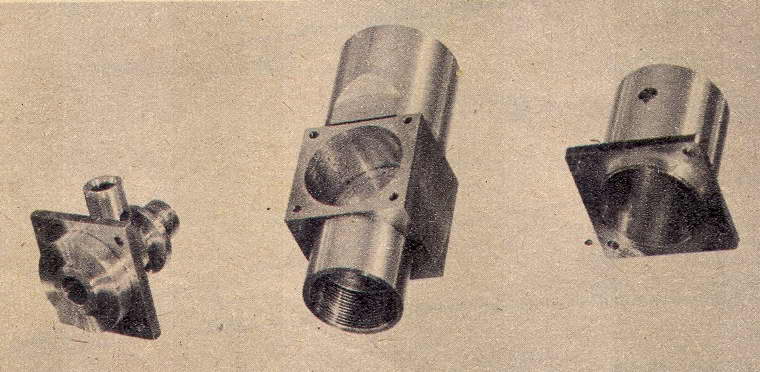
The crankcase, front bearing housing, and fuel tank are turned from 1-1/4" square aluminium bar-stock. The case is blind bored from front and back to produce an internal partition. The front bearing then fits into one end, the tank into the other. A circular protrusion is turned on top, then blind-bored and threaded for the cylinder. A slot must be milled or filed in the bottom of this cavity for the conrod swing. Note the "chucking spud" protruding from the bottom of the crankcase in the photo. This allows the case to be simply re-chucked later to make adjustments to the deck-height while retaining the previous alignment. Not a bad idea, although I'd think that a decent 4-jaw chuck would do the job equally well.
The venturi is a press-fit over the turned front housing, as is the disk in front of it that locates and secures the timer. I doubt "Locktite" existed off the shelf in 1947, so the designer did not have a lot of choice. Experience tells me that even the one to two thou interference specified for these would cause the bore of the main journal (unbushed) to close up locally, probably surprising some builders when they tried to insert the crankshaft that used to fit perfectly.

The shaft has the screw-in stud for prop mounting that I full approve of. To establish the inlet port timing, Luis took a somewhat unconventional but pragmatic approach. The crankpin is pressed in last. This simplifies turning the shaft and avoids the need for offset turning jigs. After the finished journal and web are parted off, a circle is scratched on the face of the web at the correct throw distance using the lathe cross-slide. The longitudinal position of the inlet port is established by spotting it through the venturi. After drilling the port, a line is scribed across the web 45° from the center of the port. The intersection of this line and the circle is then drilled for the press-fit of a drill-rod crankpin. I'm not a fan of this construction for beginners, but if it works and the pin ends up secure and in line with the shaft axis, it does produce a simple overhung crankshaft.
The other aspect of the shaft design that I don't like is the use of a "D" for locking the prop drive disk. It's easy to file the D on the end of the shaft, but producing the D in the disk is another matter. Worse, a half-way decent D of only 1/32" will intersect the threaded hole. If you look closely at the tip of the shaft in the photo, you'll see a missing crescent on the left where this has happened to the prototype shaft. The flat visible on the end of the shaft is the cam for the timer points (note the corresponding slot in the end of the front of the shaft journal). This requires case hardening to prevent the edges wearing and changing the dwell.
 The most unusual choice and potentially least appealing to a modern beginner is the piston and conrod construction. The designer reasoned that friction induced by poor alignment of the conrod holes and/or piston wrist-pin hole was a high-danger area for constructors. His solution was to use a ball joint for the piston, like the well-known Cox engines. So now instead of drilling two parallel holes in a conrod and one centered and correctly aligned in the piston, the builder must turn a tiny sphere on the end of the conrod and contend with fitting and fixing it to a socket.
The conrod ball is produced using a form-tool. This is made by drilling a #1 hole in a piece of 3/8" square mild steel at a 10° angle to produce front-rake. After cutting and filing away the end of the bar to intersect the hole, the mild steel is case hardened. This will produce a tool quite capable of producing a reasonable sphere on the end of the conrod (both ends actually, as the big end is a slightly bigger flattened sphere produced the same way).
The machining sequence for the conrod described in the text takes cutting forces into account and should produce a good, functional part. Being a 25, the components are relatively large. The ball is 0.213" in diameter, so there is a good chance of the beginner producing a decent job of this part.
The socket is an aluminium post that is drilled to form the ball receptor and riveted to the piston crown—the latter being turned from cast iron. Another simple tool must be made to align the socket while the pip on its end is peened over to the piston crown. The tool is then reversed to close the end of the insert over the conrod ball which is inserted inside the tool for this operation. Note that the socket cavity formed by drilling will be conical, not spherical. This will wear quickly, requiring re-setting the socket to eliminate slop. Even worse, it will change the timing.

The designer's stated intent was to eliminate an off-axis wrist pin as the source of excessive friction. Ok, I might buy that, but I think he has merely shifted the danger to the other end. As you can see in the General Arrangement CAD drawing I've produced, the crankweb and case cavity allow almost no fore-aft movement of the rod on the crankpin. So if the big end bore is slightly off perpendicular to the rod axis, the little end will displace the ball fore or aft of the cylinder axis. While the ball joint will allow the piston to assume a vertical alignment, the rod has to bend to get the piston into the cylinder. Net result is excess piston friction, binding in the big end, and swift wear of crankpin or conrod, or both.

If a conventional rod had been used, a small amount of deviation from the perpendicular for the big end hole can be tolerated provided that the little end is in line with it. Think about it. If big end alignment displaces the little end from the cylinder axis, the little end can simply slide along the wrist pin to where ever it's happiest. If both holes are parallel, friction will still be low. Achieving parallel rod holes is not hard if both holes are drilled by clamping it to something and just moving the position of the drill by the hole spacing. True, you do need to get the wristpin hole bored at right angles to the piston axis, but a decent V-block will take care of that. Overall, I must conclude that the ball-joint has more against it than for it in the context of a first IC project.
The rest of the engine is straight-forward. The cylinder is turned from cast-iron (Meehanite is specified; good luck today) with a blind-bore (see The Schroeder Victor for why I'm less fussed over blind bores for beginners). The exhaust is designed so the two opposed ports can be cut with a warding file using two turned flanges providing references for the vertical extents. From this simplicity, we progress to the transfer ports which must be cut with a 3/8" milling cutter in the inside walls of the cylinder between the exhausts (Cox-like, although used in many, many designs prior to the Cox). This could be done in the lathe with the cutter in the chuck and the cylinder mounted on the saddle. Establishing the precise depth of the cut would require a bit of careful thinking though.
The cylinder screws into the case using a 28 TPI thread. My recommendation would be choose a thread that is a multiple of your lathe lead-screw pitch. This means that you can ignore the lathe thread indicator and engage the cut anywhere without worry of picking up the earlier cut. After the two screw together, the author suggests re-chucking the case (using the "spud") to face back the seat so the exhausts orient at the sides. I'd say establishing the correct "deck-height" is more important as this sets the location of the exhaust and transfer port edges in relation to the crankshaft axis, and hence sets the timing.
Finally, like all square bar-stock engines, we come to the mounting problem. The designer suggests brackets folded from aluminium sheet that fit under the fuel tank mounting screws. This is practical, if not exactly elegant. I shudder to add that for testing, he left the spud in place and gripped this in the bench vice! The COTS timer and NVA, plus a V3 spark plug complete the engine. An mentioned earlier, you can no longer wander into a model store and hope to find an ignition timer assembly. The style shown can be replicated from bar-stock, but the beginner would be well advised to fit a simpler one that does not require watchmaking skills, such as that Roger Schroeder designed for his Victor 09 design.
The compression ratio of the SIMPLEX 25 works out at 8:1 meaning it should run quite well as a glow engine as well as the spark ignition it was designed for. The engine has size going for it, making many of the machining operations easier for the beginner. However, this size may put it beyond the capacity of today's bench-top machines like the Sherline and others. Taken overall, a beginner who wants to make a spark ignition engine would be better advised to build the Victor. But provided they understand and feel comfortable with the areas of difficulty, the SIMPLEX should prove a satisfying project. The magazine plans are not error-free. The worst offence being the bore in the case top for the cylinder. This needs to be 9/16" deep rather than the 1/2" shown if you want the engine to actually turn over. A fully redrawn set of CAD plans, complete with detailed drawings for the COTS parts (timer and NVA), are available for free download in the Members' Section to MEN supporters. Non-members should contact me for pricing.
Afterword
 The SIMPLEX design briefly re-surfaced in 1978 as a limited edition production from John Morrill. Billed as the Mk II, the Morrill SIMPLEX is rather attractive in an angular sort of way, assisted by the very pleasing color contrasts employed. The obvious design changes are a screw-in head (no blind-bore to hone) and a different timer that appears to be based on a commercial points assembly (avoid the COTS-no-longer problem). As no "beginners" are involved, milling is permitted and the case gets conventional mounting lugs and some bevelling of the bottom edges. The venturi profiling is simplified and the fuel tank is a "vintage replacement" part for the Hurrican 24. The finish on the case has been produced by blasting and clear anodizing. Not so obvious is the conventional wrist pin piston and chromed crankshaft. About 50 (or 115) engines were built, serialized from #8 up [1]. John's #001 engine was per the plans. Over the next six, he made changes, including replacing the ball joint with a conventional wrist pin, until he was happy with performance and appearance. Production then started. All these ideas are worth considering for a modern project, provided you are not an absolute beginner.
References
| [1] | Dannels, T: Americal Model Engine Encyclopedia, Model Museum, Buena Vista CO, USA, 2005, p216. |
![]()
Back to the Model Engine News Home Page
Please submit all questions and comments to enquiries@modelenginenews.org