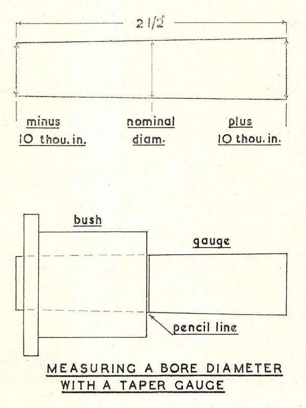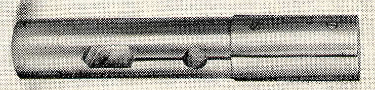
Fig 1.
Machined bearing surface.
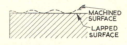
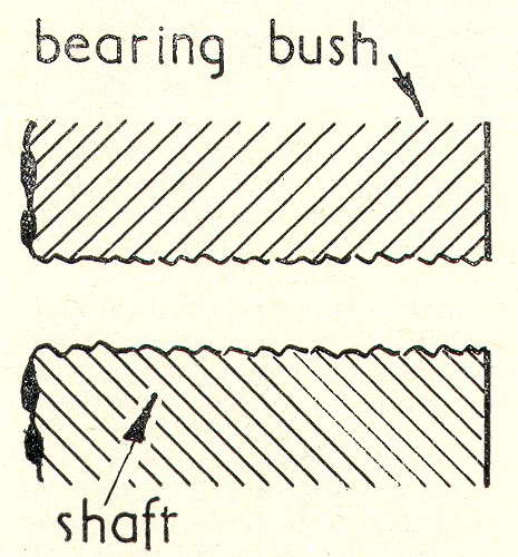
Fig 2.
Surface lapped after machining.
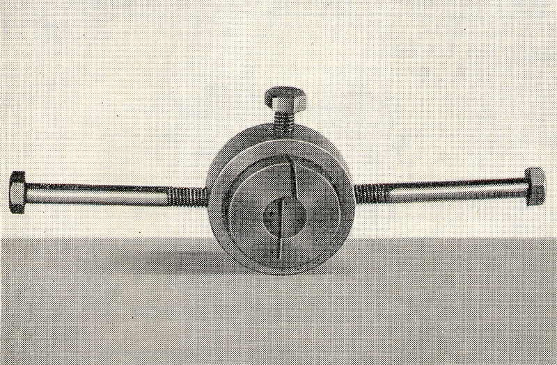
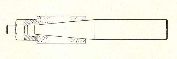
Fig 3.
Cast-iron lap and its holder.
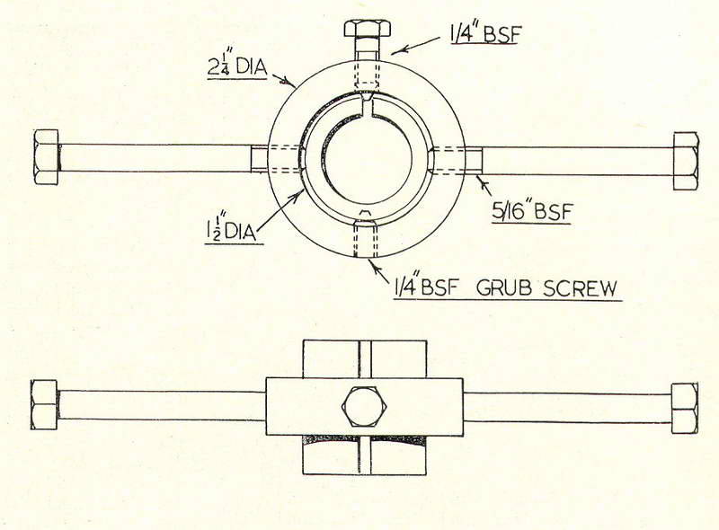
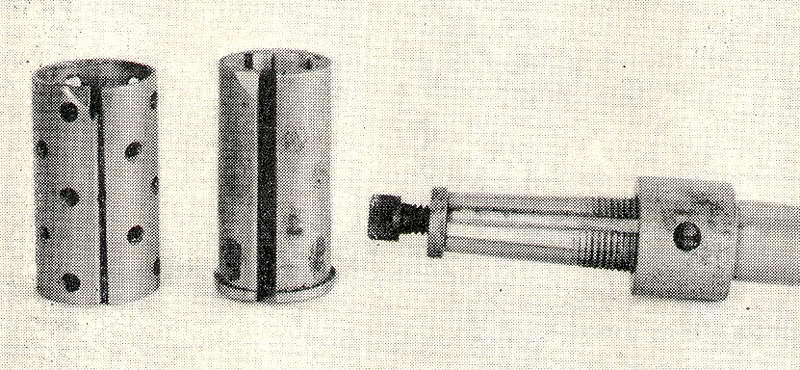
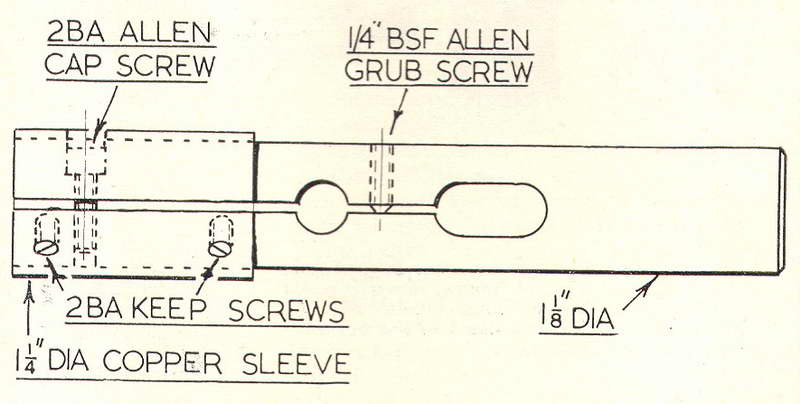
Fig 4.
Lap holder.
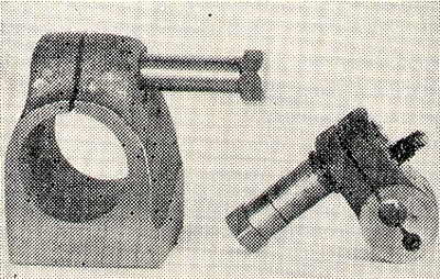
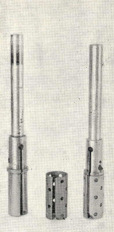
Fig 5.
Laps made from castings.
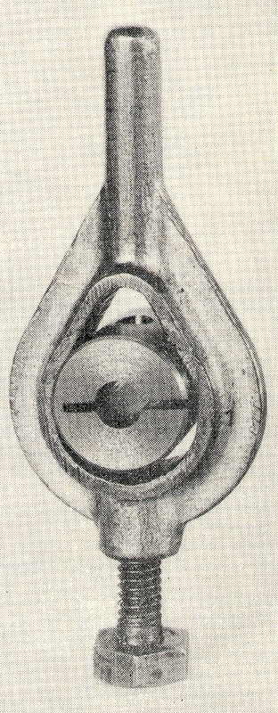
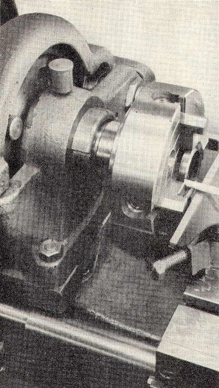
Fig 6.
Lap in a lathe carrier.
LAPS AND LAPPING
IN the workshop, lapping usually consists in fitting bearing bushes and their spindles to a higher degree of accuracy and finish than can be obtained by ordinary machining methods. It is carried out by charging a metal arbor or sleeve with an abrasive and working it, in turn, over the mating surfaces of a bush and its spindle respectively.When highly magnified, the surface of work turned in the lathe will show a continuous series of ridges, faintly resembling a fine-pitch screw thread. Moreover, the lathe is a copying machine and, as such, reproduces on the work any inaccuracies present in its mandrel and bearings, as well as those occuring in the sliding members. Because of this, from a geometric standpoint, the ordinary lathe can hardly be expected to turn exactly parallel or to produce truly circular work.
Nevertheless, these errors can be corrected by hand lapping and, in addition, the operation will produce a finish superior to that obtained by other methods. Where, as represented in Fig. 1, the bearing components are merely machine-finished, contact is made between the crests of the ridges left on the work surfaces; these may penetrate the oil film, causing metal to metal contact. The attrition of these high spots may result in scoring of the bearing surfaces and possibly seizure.
Evidence that this process is taking place is shown by blackened oil exuding from the bearing, due to the presence of suspended metal particles. Clearly, a bearing fitted in this way will soon develop looseness thus defeating its primary object of maintaining exact alignment combined with quiet running even at high speeds. On the other hand, a correctly-fitted bearing with lapped surfaces, as represented diagrammatically in Fig. 2, will run quietly and with a minimum of friction. The oil will remain clean and need only occasional replenishment.
A typical example of lapping operations carried out in the workshop is the finishing of a steel spindle and its cast-iron bushes to provide an accurate, close running fit, leaving only sufficient clearance for the oil film to prevent metal to metal contact.
The shaft is first turned in the lathe to a diameter 1 or 2 thou greater than the finished size, depending on the surface finish obtained; this is to allow for lapping to size.
A useful and easily-made type of external lap is illustrated in Fig. 3. It consists of an inner cast-iron sleeve mounted in a simple form of holder. After the sleeve has been turned all over, drilled and bored slightly under size, the bore is rendered smooth and parallel with a hand reamer. The lap is finally slit obliquely through to the bore, and only partly slit in the opposite direction on the other side of the bore. This allows the lap to be adjusted by the pressure screws.
The holder is made from a mildsteel ring and carries two long screws which compress the die and also serve as handles. The upper, short screw has a coned point to engage in the cross slot. Further support is given to the die by the pointed grubscrew, which seats in a dimple drilled in the opposite surface. Constructional details of the lap and its holder are shown in Fig. 4; but these dimensions can be altered as required.
When in operation, adjustments to the lap are made by tightening the upper coned screw to expand the die; tightening the long screw closes the die and secures it firmly in the holder. All four screws should be tightened when the final adjustment is made.
The two improvised laps, Fig. 5, were made from parts sawn off discarded iron castings and, although seemingly somewhat primitive, they proved fully effective. The larger lap, having a bore of 1-1/4 in., was used for lapping the spindle of a vertical milling machine that was made in the workshop. As shown in Fig. 6, a lathe carrier can on occasion be used for holding a lap, but there is no provision for expanding the die.
Lapping compounds in wide variety and suitable for all lapping operations are manufactured by the Carborundum Co. of Trafford Park, Manchester. The carbon silicate compounds, denoted by the letter C, are fast-cutting and suitable for finishing hardened metals. The H series of Aloxite products are slower in action and are intended for lapping softer metals to a high finish.
The grit sizes of these compounds range from 60 to 700 in the C series and from 240 to 700 in the H series. The carrier medium for suspending the abrasive grains may be either fluid oil, designated OF, or water; but oil is preferable for ordinary workshop use, since the consistency remains constant and the fluid does not tend to dry out.
For most lapping operations a small stock of compounds will be sufficient, including C240-OF and C500-OF, with H700-OF for giving a polished surface finish. After the spindle has been turned to a good surface finish and slightly in excess of the nominal diameter, the lapping operations can be begun.
The lap is adjusted to slide freely along the spindle after its screws have been tightened. To hasten the. operation, coarse-grained lapping compound is first applied thinly to the spindle. With the work rotating at a moderate speed, the lap is guided by hand over the whole length of the spindle, and the measure of resistance felt will indicate any high spots due to lack of parallelism. These areas must be mainly worked on until the lap moves smoothly from end to end of the spindle. In time, the abrasive grains of the lapping compound will become blunted and will have to be replaced by fresh paste.
Use the micrometer to measure the diameter of the work and check that all toolmarks have been removed; this should only be done after thorough cleaning with paraffin. Where necessary, lapping is continued with fresh compound, after the lap has been adjusted to take up wear.