IN THE WORKSHOP
by "Duplex"
No. 97—Micrometer Stands
(click on images for larger pictures)
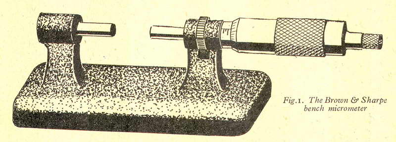 THE ordinary workshop micrometer is commonly used in two ways: either it is held in the hand and applied to work that is mounted in the lathe or gripped in the vice, or small parts such as screws are measured by holding the micrometer, as well as the work, with the fingers of one hand and employing the other hand to turn the adjusting thimble. The latter, three-purpose method is quite generally used and with practice gives good results; nevertheless, the hands work more efficiently and have a better sense of touch when relieved of muscular strain, and when, at most, performing a single delicate operation with either hand. It is therefore an advantage to have the micrometer supported, when gauging small parts, so that the hands are employed solely in lightly holding the work and adjusting the micrometer. The bench pattern micrometer, illustrated in Fig. 1, is intended for this purpose, and to give stability it is formed with a heavy, cast base. This instrument is, however, too heavy and cumbersome for convenient handling when measuring work mounted in the lathe.
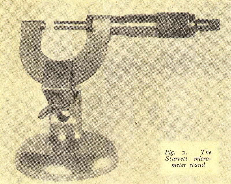
To enable the micrometer both to be applied to parts mounted in machine tools and to be used to the best advantage on the bench, a form of stand is usually employed that allows the micrometer to be quickly clamped in place or removed for handling. The Starrett micrometer stand, shown in Fig. 2, is made to serve this double purpose, and a single bolt and wing-nut is fitted both for clamping the micrometer and for locking the pivot joint which allows the instrument to be tilted to a convenient angle for reading the scale. A further advantage of using a stand of this kind is that there is then no need to lay the micrometer on the bench or on the lathe bed where it is liable to suffer damage; instead, the instrument is always kept mounted in its holder, which stands either on the bench or on the lathe tool stand.
Making a Micrometer Stand
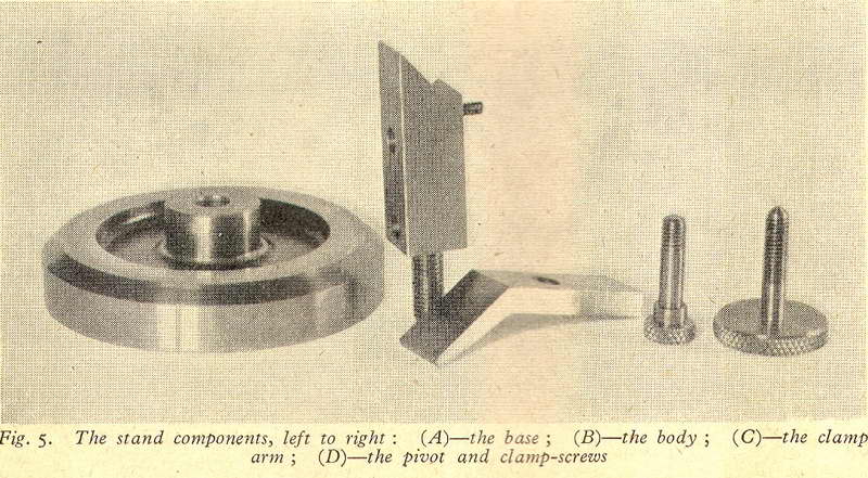
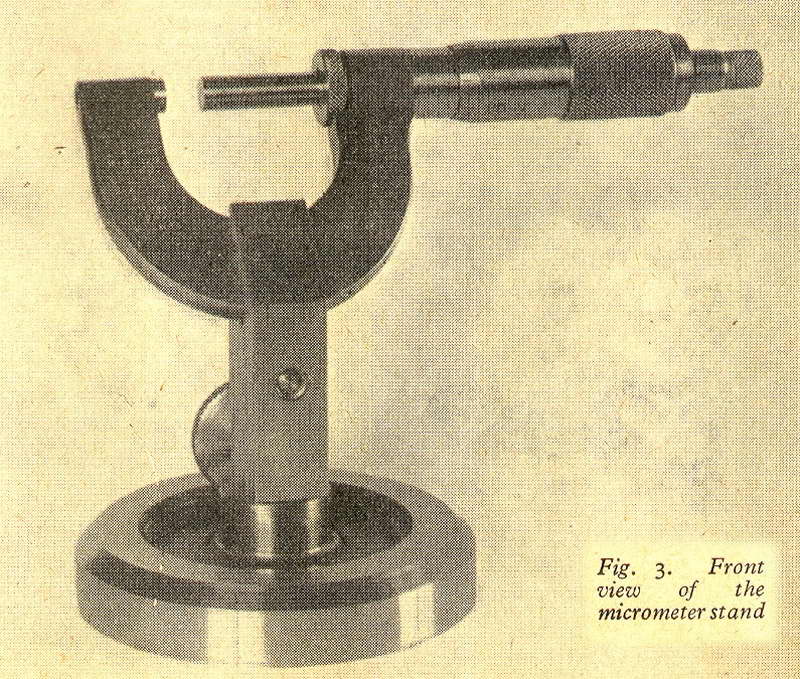 As a result of making enquiries of tool merchants, it appears that micrometer stands are no longer obtainable in this country. Recently, a second micrometer stand was required in order to save the inconvenience of having to use a single stand to serve two or more micrometers. It was decided, therefore, to make a simple form of this appliance that could easily be built from scrap material and yet would do all that was needed. As it was found that a single position of the clamp was sufficient to enable the micrometer to be easily read, a fixed form of clamp was employed which did not permit of angular adjustment. To keep the front of the stand free from obstructions, the two screws actuating the clamp were placed at the back of the holder. The finished stand is shown in Figs 3 and 4, and the component parts are illustrated in Fig. 5 and in the accompanying working drawings.
(A) |
(B) |
(C) |
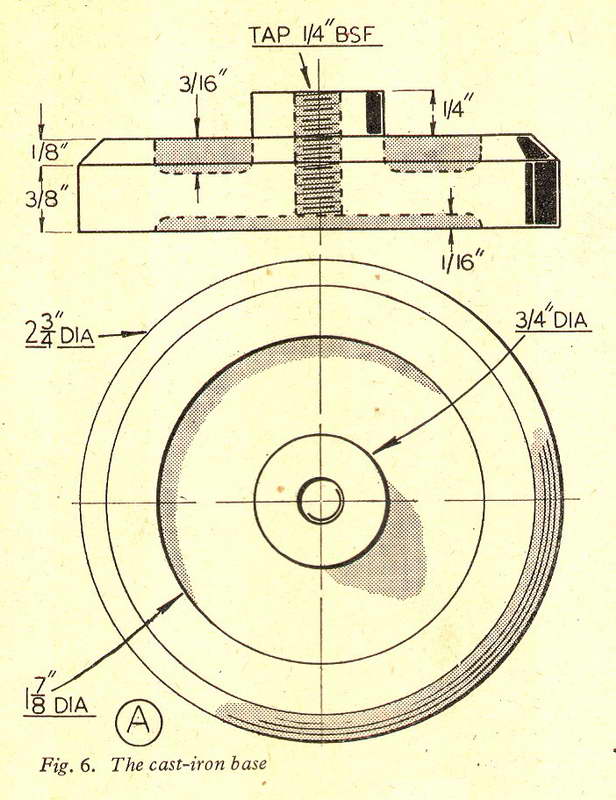
The Base (A)
This was made from a discarded iron casting originally intended for the jockey pufiey of a drilling machine. The precise dimensions of this part are, of course, unimportant, as long as the casting or other material used is heavy enough to ensure a stable mounting for, say, a 2 in. micrometer. The casting is first gripped in the ,chuck for facing the upper surface and boring and tapping the central hole; at the same time, the recess is turned to a good finish with a round-nosed tool.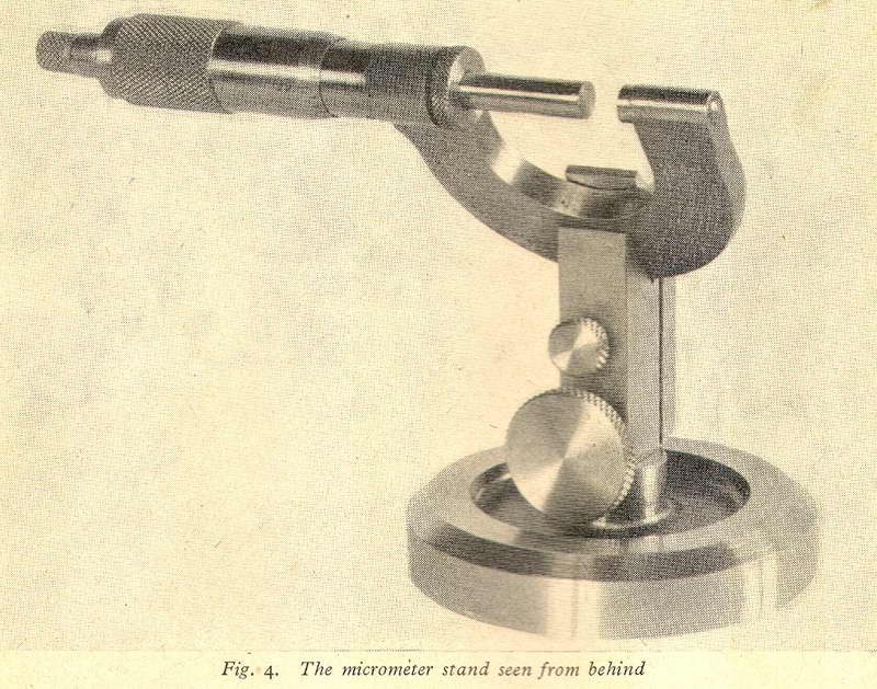 Next, the work is reversed in the chuck for facing the underside, and, to give greater stability, the rim is machined to stand higher than the central portion of the casting. To finish the machining, the casting is mounted on a threaded stub mandrel with its upper surface outwards so that the periphery can be turned and the bevelled edge formed. If a tungsten carbide tool is used for the turning operations, the work can be run at moderately high speed, using the direct drive to the mandrel; in this way, a smooth machined surface should be obtained, which will lessen the rather laborious work of polishing. The polishing operation is started by removing all tool marks with a discarded, smooth file applied to the revolving work, for if a serviceable file is used it is almost sure to be blunted, particularly where the casting is of hard material. The next step is to cover the file with a strip of coarse abrasive cloth and to continue the polishing, using, meanwhile, plenty of thin oil and applying firm pressure, until all file marks have been eliminated.
The final polish is given by using a finer grade of abrasive, but oil must still be applied or a glazed appearance will result which looks rather unsightly. Before removing the work from the lathe, all oil is cleaned off with petrol or lighter fluid in order to prepare the central recess for painting. The paint is applied with a small brush while the casting is revolving at a moderate speed; moreover, if the work is kept turning for a time, a quickdrying paint will be able to set, and paint runs will in this way be avoided. Optical ebony black gives a pleasing, matt finish, but if glossy cellulose enamel is. used, the surface, when dry, should be treated with liquid metal polish in order to subdue the highly glazed finish.
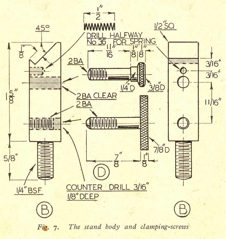
The Body (B)
 This part is made from a short length of 1/2 in. square mild-steel, threaded at its lower end to screw into the base casting. On making a trial setting with the Starrett stand, it was found that the micrometer could be read most conveniently when mounted at an angle of some 45 degrees; the upper end of the body was therefore machined to this angle in the shaping machine, but this face can quite well be either milled or filed to shape. Should the micrometer be mounted to lie more nearly horizontal, the clamping face on the body will be shorter and, moreover, a heavy micrometer would then be more liable to overbalance. The step on which the bow of the micrometer rests must, of course, be made shallower than the thickness of the bow to enable the micrometer to be securely clamped. A short length of stiff. petrol lighter spring is housed in a hole drilled in the body above the pivot screw, so as to open the clamp and free the micrometer when the clamp screw is slackened.
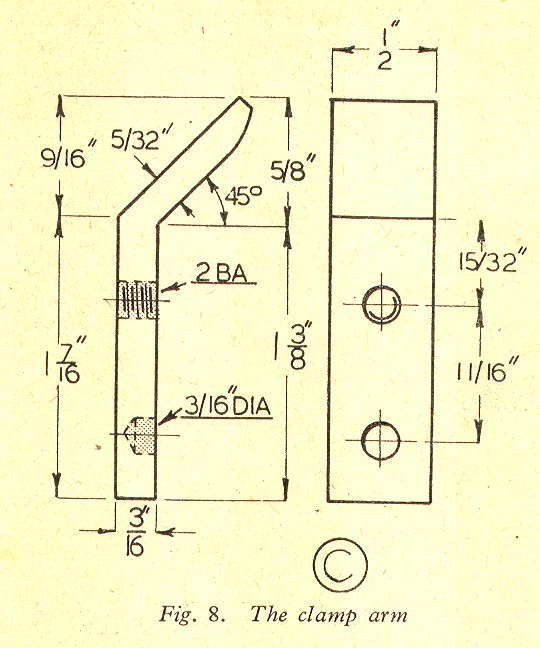
The Clamp Arm (C)
The clamp itself works on the principle of the ordinary toolmaker's clamp, but it is rather less efficient, as the actual clamping surface lies at an angle to the actuating screws; nevertheless, a 2-in. micrometer is held quite firmly with only moderate tightening of the clamp-screw. The clamp arm is cut to shape with hacksaw and file, and it will be noticed that the clamping surface is made slightly curved towards its tip to allow for the rocking movement imparted when the clamp is tightened; for the same reason, the hole to receive the small pivot screw is threaded for less than the full thickness of the material. The recess in which the lower clamp-screw engages is deeply drilled with a centre drill in order to afford, a good bearing, and so check any tendency for the clamp arm to rise when the clamping pressure is applied. When drilling the clamp arm, it is best to secure it in position on the body with a toolmaker's clamp; the body will then serve as a drilling jig for accurately locating the holes.The Actuating Screws (D)
When mounting a micrometer in the stand, the pivot screw is tightened until the clamp is closed on the bow, with the lower limb of the arm lying approximately parallel with the body. The pivot screw acts, therefore, merely as a setting screw, and its head is made small to give a neat appearance. Next, the clamp-screw is tightened until the micrometer is found to be firmly held. However, if there is any difficulty in obtaining a good grip, a different setting of the pivot screw should be tried to alter slightly the angle at which the two clamping surfaces meet. To get satisfactory clamping with only moderate finger pressure, the knurled head of the clamping screw is made of large diameter. When the clamp has been. set, it is only necessary to give the clamping-screw a partial turn in order to remove or reclamp the micrometer.As shown in the drawings, the body is drilled for a short distance to the clearing size of the shank of the clamp-screw; in this way, as is usual in instrument work, a better appearance is obtained, as the threads on the clamp-screw are then hidden.