Building the Morton M5
![]()
See the M5 Reference Page for a description and history of this engine.
 THIS PAGE UNDER CONSTRUCTION
- Motor Mount
- Cam Followers
- Push Rods
- Rocker, big end and wrist pins
- Valves
- Crankshaft
- Prop Hub (flying)
- Master Rod
- Link Rods
- Rocker Arms
- Valve Cage Nuts
- Valve Spring Caps
- Valve Cages
Motor Mount
 The M5 motor mount closely follows full-size practice. Three sleeves attach to the M5 on lugs integral with the gearcase, tapped 6-32. These lugs are not equally spaced--the top two being 128 degrees apart. A truss made from 1/8" steel rod ties these to four sleeves for attachment to the firewall. The drawing calls out steel tubing for these members, but not even original Morton mounts use it. This design is light and provides space for the accessories at the rear of the engine, while giving a very rigid mount when all the bolts are tightened up. Naturally, a design like this calls for something stronger than solder. I chose to silver braze the joints--a process that requires a lot of heat.

 The seven bushes need to be securly jigged in place for attachment of the truss rods. I'd had this brilliant idea of using old hard disk platters for this job. Unfortunately (or fortunately, as it turns out), their diameter was just too small for the firewall side, so a 1/8" plate of anodized aluminum was cut. The standoffs were made from 1/4" aluminum rod with the motor ends turned down to 0.15" for 1/8" to locate the stubs accurately. These pillars are secured with 4-40 screws at either end. The firewall sleeves are held by 6-32 steel bolts. These photos show the sleeves jigged up, ready for attacment of the truss rods.

 The truss rods were cut roughly to length from 1/8" steel, then beveled on the bench grinder to approximately the right angles by cut 'n try. When they were about right, the beveled faces were made concave on the edge of the grinding wheel. This does not have to be perfect, but the closer the better (the factory made Morton made mounts hardly bothered at all). Next comes the problem of holding this all in place for brazing. I've used soft iron wire of the type used to make paper flowers. It was not perfect--in fact very frustrating, but it worked in the end. The flat things are magnets (more disk drive refugees). This was fine while the heat was localized, but the bigger flame heated the magnets past their Curie point--where they cease to be magnets.
Some time back, I picked up a trick to prevent silver solder going where you don't want it to: just paint these areas with typewriter corrector fluid. Thet's the white stuff visible on the bolt heads that prevents them becomming a permanent part of the mount in these shots. The other stuff is the brazing flux applied to all joints so any heat conducted from an adjoining cluster does not oxidize the surfaces yet to be heated.

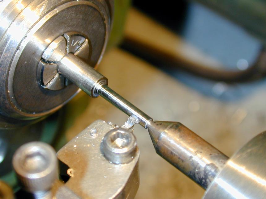
Multi cylinder engines involve a lot of repitious work. To complete the gear case assembly, we need 10 cam followers. As designed, these are simply 0.675" lengths of 5/32" drill rod, turned hemispherical on one end, with a hemispherical cavity on the other to take the valve push rods. To assist with all this repitition, I took a couple of days out to build a lathe spindle back-stop. This permits parts to be quickly and accurately repositioned in the chuck or a collet and will hopefully take some of the tedium out of all the work to come. Making the tappets is hardly worth describing, but perhaps the tooling used is. This shot shows the 12 finished cam followers. Behind them on the left is a HSS tool ground to a 5/64" radius using a chain-saw sharpening bit in a Dremel hand-tool and a 5/32" drill bit shank as a gauge. Not too accurate, but it does not really need to be. To the right is a 3/32" D bit with a hemispherical end used to form the pits for the push rods. I drilled almost to depth first with a #1 center drill, then followed this with the D bit reamer. As I have two tailstock chucks, this was done by chuck swapping--a lot faster than changing the bit in the chuck! The finished parts could be hardened, but I'd rather they suffer the wear than the cam lobes, so they'll be left soft. To machine the ends, the form tool is just plunged in--a process that again disclosed one of life's mysteries (to me, at least). Plunged in dry, the tool cuts well and produces a good finish that buffs up very nicely. If any cutting lubricant is applied, the tool immediatly stops cutting and the finish galls up. I've noticed this before where a "form tool" is being used and I've no idea why?!
The M5 valve push rods are made from 3/32" drill rid, 1.5" long (though an original Morton part I measured was 1.476" long). As the motion of tappet, push rod and rocker arm are not linear, the ends need to be spherical so the different angles assumed by the 3 parts can be accomodated. The only practical way I could figure to make these parts was using a "form tool"--a piece of HSS ground to compliment the shape required. This shot shows the tool, and to the right, a short trail piece showing two (of several) attempts at the desired shape, along with the lifter the end must be able to fit snugly inside with 5 to 10 degrees of conical movement available. At the bottom of the picture is an original Morton valve rod and above that, my first attempt.
Even though I have a Quorn Tool and Cutter Grinder, setting up a diamond dresser to form a 3/64" Radius on a thin grinding wheel did not work too well. The final shape was made and polished using a cut-off wheel in the trusty Dremal hand tool, taking very gentle sweeping passes around the rough shape until a piece of 3/32" drill rod seemed to fit neatly in when viewed under low magnification. Form tools induce much higher cutting forces than normal lathe tools, so the overhang from the jaws of such a small diameter work piece must be kept minimal to minimise the chances of the part being bent. This shot shows my trail setup in a 3/32" collet. It works well provided the feed is kept very gradual and is never paused with the tool in contact with the part as this quickly work hardens the surface. I've found that applying cutting oil to form tools like this also stops them cutting and immediatly induces work-hardening too (at least that's what I think is happening). At any rate, the finish is good, buffs up well on a Scpthc-Brite belt and appears more spherical than the Morton part (though in fareness, that M5 rod comes from an engine that has run, so it may be worn). The rods will be left in the soft state.
Well, just to show no plan is perfect, here we see the form-tool casulties. The corresponding pile of survivors was a miserable seven (from twenty candidates). Advice from wise machinists (Eric Offen and David Owen) was to reduce the top rake to zero and make sure the tool was exactly on center height. Alas, the reject rate was no better, so with stocks of 3/32 drill rod rapidly diminishing, a better plan was most obviously needed.
The plan, for a change, worked. To conserve material, the production run will be two batches of 10 made from five 3-3/4" lengths of 1/4" stainless rod. Working on each end produces 10 valves, so after being cut off (in the band saw), the remaining length of rod (about 4") will give another 10 valves and enough in the middle to grip in a collet. Final facing, trimming to length and retaining clip grooving will be done collectively on the 20 valves. The photos show the basic steps. Batched operations were governed by tool, or set-up changes:
 Initially I used the smallest head my Sievert gas tourch has. This prooved just too small to adequately heat the joint cluster and the attached plates, though I persevered and did two joints with it. The next size up produced sufficient heat, but with so much peripheral heat that the disk drive platter suffered badly as you can see here. Fortunately, the standoffs prevented anything shifting, so I got away with it. The final step was to clean up the oxidization using soapy water and kitchen type ScothBright pads. Slow, messy work, but it gets the job done.
Cam Followers

Push Rods


 Ken Croft suggested a spherical turning attachment and as I'd made one to the Radford/Thomas/Hemmingway design some years ago to make ball handles for the Quorn, I decided to see if it could make real small balls. The photo here shows the general design: the tool bit cuts tangentially and is rotated in an "up and over" motion to form the sphere. The tool carrier is adjusted by a fine lead screw (turned by the Allen key visible in this shot). The problem is that the head requires good clearence around the material and 3/32" drill rod with that much over-hang would never stand the cutting forces.

 The solution was simple enough. A 3/8" stub holds the rod supporting it rigidly with only 1/4" of material protruding. After a couple of trials on the many failures to proove the technique, the remaining 14 rods were machined with no failures--even though the process was slower than using the form tool (when it worked!). The seven rods on the right were turned this way. The others are mixed and it's hard to tell which is which. Anyway, I now have two M5's worth of push rods.
Rocker, Big End and Wrist pins
All these parts are made from 0.125" diameter water-hardening drill rod (called "silver steel" in the UK because of its appearence--there's no actual silver in it at all). I thought these would be just simple, boring repitition work. How wrong can you get.
 Both the rocker and big end pins are designed to screw in on one end. The thread is 2-56, so the diameter must be reduced and the thread cut to a undercut sholder. To ensure accurate alignment, the female threaded end is counter bored 0.125" for a short distance so that both ends of the pin are supported in a reamed hole. The threaded length is only 0.095" long (under cut 0.016" wide at the sholder). Very fiddly--watchmaker stuff. As this is about the same length as the tapered lead-in on my 2-56 die, first attempts were made running the die on backwards using a tailstock mounted die holder. It was Yet Another Disaster--eight failures in nine attempts. This shot shows, left to right, a failure, an uncut blank and the single success. I'm thinking of changing the design to use full floating pins, retained by E clips at either end. Grrr...
 After the rocker pin fiasco, I felt I needed a success or two to maintain momentum and enthusiasm for the project, so the next (and simple) task chosen was the wrist pins. These are just 0.515" lengths of drill rod, drilled through 1/16" (and am I ever glad I took a couple of days out to make that lathe spindle back-stop!)
 The wrist pins are full-floating, so their ends should be smoothly rounded to prevent scoring of the cylinder liner, but the pins are drilled through (for lightness, I think), so rounding is not practical. Although the drawings don't show them, I decided to make little brass end pads for the wrist pins. These will be glued in with LockTite and profiled. Ten pins, 20 pads, one hour: 3 minutes per pad that includes a tool change from brass turning tool to thin (0.020") part-off tool. Just as well I don't do this for a living!
 The pins that retain the slave (or link) rods in the master rod are called link pins. Morton designed them the same way as the rocker pins with a 2-56 thread to an undercut sholder. As there have been instances of these unscrewing and jamming up on the crankshaft counterbalance cut-outs (I shudder to think of the damage at 5000 rpm), Bruce Satra suggests making them full floating as well, retaining them in the master rod with thin steel washers--the whole thing sandwiched between front and rear crankshaft webs. So that's how they've been made here. The cunning retention method for the fully floating pins is shown in the Link Rods section. This photo shows, as usual, two engines worth of pins.
Valves
 Valves are not something I've made before and the Morton valves are tiny! They are 0.797" long with a 0.092" stem and a 1/4" diameter head, 1/16" thick. The groove for the retaining clip is 0.020" wide and 0.010" deep. The plans call for 4130 steel, hardened to Rockwell "C" 33-38. Lacking a heat-treat oven, hardness testing gear and being worried about the stems warping, I decided to make them out of stainless steel as seems to be "modern" practice. The plan was to make one valve to experience all the processes involved (ie, all the things that can go wrong), then devise the mass production process (I need 20 of the little buggers, plus some spares). Next, do a trial of the "production-line process" -- say 2 valves, and finally, make 20 more!
 Step 1 Step 1 |
 Step 2 Step 2 |
 Step 3a Step 3a |
 Step 3b Step 3b |
 Step 3c Step 3c |
 Step 4 Step 4 |
 Step 5 Step 5 |
 Step 6 Step 6 |
 Step 7 Step 7 |
 Step 8 Step 8 |
 Step 9 Step 9 |
Step 1
A 60 degree point is cut on each end of the blanks. This will be applied to a female center held in the tailstock to support the thin stem during finishing cuts.Step 1a
The trial valve showed that it was very helpful to reduce the first 1/16" of the cone to just on, or 0.001" under finished diameter to provide a resting space for the tool tip at the start of the finishing passes. Making the stem over required length allows this bit and the pointy bit to be trimmed away later. The step before the point can be seen in the photo for Step 2.Step 2
The approximate sholder point is scribed using odd-leg calipers ("Jenny" calipers in the USA) and the blank is roughed down to about 0.15" back to this mark. This cut is made unsupported as neither finish nor consistant diameter are needed. I ended up taking two 0.015" and two 0.010" cuts with a roughing tool ground to the style shown in Martin's book Tabletop Machining.Step 3a
The tailstock support is now brought up and the blanks finished to size taking 0.005" passes with a tool ground to a tip radius of 1/32". When the blank reaches 0.020" of final size, each pass is run twice at the same setting to allow for springback of the work. It's remarkable how much that second pass cuts with no change in the tool tip position. You can also see here how the little run-in area helps position for each pass (a valuable lesson learnt making the first trial piece).Step 3b
No, not a lap, just a short length of bronze reamed 3/32", as the valve cages will be, that is used as a go-no-go gauge when the cross slide dial and measuring gear reports final diameter is being reached. We are after a close sliding fit--the drawings say 0.092", plus 0.000", minus 0.001" to fit in the reamed 0.093" valve guide.Step 3c
This shot gives an idea of the two step process. At this stage all blanks are ready to have the 45 degree valve seat cut. The longer blanks will then become shorter ones like the one at the top of the stack. Leasson learned here was that I'd been too Scotch on blank length. I should have allowed at least 1/8" more on each valve for more stem length. Some were so short that they reached final length before all the rough tip was faced away. Just as well I made spares...Step 4
With the compound set over to 45 degrees, the valve sholders are cut. The drawings show that 0.015" of the head holds to the 1/4" stock diameter before this taper starts, meaning 0.048" of the head thickness is tapered. Right or wrong, I decided this was not too critical, so set the odd-leg calipers to as close as 048 as I could get and used these to slightly scribe a circle from the sholder. The head was then faced until the line just disappeared. I could not figure a way to accurately measure the result, but it *seems* to be ok within a couple of thousanths.Step 5
At this point, all the part finished valves are parted off (in the band saw) leaving the head oversize. Steps 1 to 4 are then repeated on the shorter blanks, and those sawn in half. Maybe that should be called step 5, but anyway, here the valves are gripped by their stem in a 3/32" collet and the head faced back. The little brass washer behind the head is countersunk at 90 degrees to support the head during facing. It was also intended to speed up this process by positioning the valve a known distance from the collet, but due (I think) to the way Myford collets close, it did not give sufficient accuracy. So, each head got faced by mk 1 eyeball to close to size, then removed and measured to determine how much had yet to be faced off. Facing all the valves took about an hour, so not too painfull.Step 6
For this step, the valve is inserted from the back of the collet and gripped with minimum protrusion for facing back the stem to the overall length of 0.797". To simplify this, the spindle back-stop is brought up to touch the valve face of a finished part allowing the saddle to be locked and the compound slide zeroed at the finished length. All valves are run through at this setup.Step 7
The last step is to cut the retaining clip groove. The tool here has a 0.020" tip and another hour went into groove cutting, including grinding the tool on the Quorn. I subsequently found that the burr raised by the tool was a problem, so another tool with a 0.024" tip was ground and all grooves cut again which removed the burr. As the valves are all to final length at this stage, the groove can be positioned by touching the left face to the tip, then winding the compound slide 0.058" towards the headstock. Again, minimal protrusion of stem from the collet uas used to maximise rigidity of the work piece.Step 8
I'm departing from the Morton drawings again on the valve retention method. Morton used tiny circlips made from 0.015" piano wire, OD 0.118" with a 0.015" gap and I don't fancy making those. Instead I'll use a thin C clip like Eric Whittle uses on his 4-stroke designs. The C clips are made from 0.156" diameter drill rod and will be hardened and tempered. First, the rod is drilled to the diameter of the groove (1/16"). Eric Whittle then uses the lathe saddle wheel like a shaper to cut a slot down to the drilled hole. I've never had any great success doing this, but have found that by slitting the rod first with a Dremel part-off wheel, the shaper trick works well to dress up the slot. After the slot is cut, the thin groove cutting tool is used to part off clips 0.015" thick. Lots of spares are made as they have a tendency to evaporate.Step 9
The parting off raises lots of burrs on the clips, so each needs to be cleaned up by sanding on fine glass paper and a flat surface. To preserve my finger prints, I use a small "rare earth" magnet liberated from a dead hard disk drive to hold a trio of clips for this operation. After this step, the clips are hardened, polished again, then tempered to blue.Crankshaft

 The M5 crankshaft is relatively standard except for the drilled crankpin and huge counterbalance. The photo on the left shows the shaft and bearings received with the original Morton kit; the next is a shaft made by Bruce Satra of Vernal Engineering. This one I bought with the castings in 1995 when I found the prospect of machining it daunting. Today, with over 30 engines under my belt as it were, it would pose no special challenge apart from machining the throw on the accessory drive crankshaft to match. As the pin on this shaft engages in the hole in the crankpin, it is essential that the throws match exactly to prevent binding. This would be simple if they could both be machined in the same offset jig (as depicted in the AHC Construction series), but as the journal diameters are different, this is not possible.
 Also evident in the photos is the difference in the counter weights. The Vernal shaft is per the latest factory drawings, the other, using photos in ECJ of the various factory made shafts, is the earliest Morton design, before they started using forgings as the blank with an integral counter balance. I suspect this engine will vibrate badly because of this, so I may end up making shafts yet. Balancing radial crankshafts is much more complex than single cylinder engines as torsional resonance comes into the picture. I won't go into this in any detail, but if you'd like to read how Pratt and Whitney attacked this problem on their 18 cylinder R2800, visit the The Aircraft Engine Historical Society web site. Bruce collaborates with fellow Ozzie, Bob Roach, the designer of a scale P&W Wasp 9 cylinder radial for which Bruce provides the castings. Recently Bruce sent me yet another Morton crankshaft drawing. This one has the balance mass calculated by Bob and would be the definitive one to follow.
 The M5 bearings are "sealed" types, but that just means they are fitted with dust covers. These are not enough to retain the negative pressure required in the crankcase and the bearings also need lubrication. As far as I've been able to ascertain, Morton removed the inner seals and packed the area between the bearings with "cup grease" (whatever that is!) Here are the bearings and the spacer. One bearing has been packed with a "hi-speed" bearing grease, and though it's been rotated a lot, I'm sure there's still air on the other side of the ball cage.
 After the bearings are packed, the stack is pressed onto the shaft. Here, as usual, I'm abusing my mill/drill and chuck as a light duty press. Odements of off-cuts are arrayed above the outer bearing so the pressure is all on the inner race parts and spacer. The shaft rests on a small wooden block to prevent damage to its web.
Next the space between the bearings gets packed with grease and rotated to work any trapped air bubbles to the surface.
After the bearings are packed, the stack is pressed onto the shaft. Here, as usual, I'm abusing my mill/drill and chuck as a light duty press. Odements of off-cuts are arrayed above the outer bearing so the pressure is all on the inner race parts and spacer. The shaft rests on a small wooden block to prevent damage to its web.
Next the space between the bearings gets packed with grease and rotated to work any trapped air bubbles to the surface.
 In the background, you can see the two-step housing for the bearings in the nose of the crankcase. When the bearing/shaft assembly is pressed home, the grease will pack into this area, hopefully preventing air ingress around the shaft. I'm told that over time, petrol will permiate the inner race "seal" and the negative crankcase pressure will leach out the diluted grease. Eventually, an air leak will develop and the engine will cease running, requiring disassembly and re-packing.

 The bearings are a press (interference) fit into their housings, but as the case wall are very thin here, it is prudent to heat the case before pressing the bearings home. To do this the nose of the case is emersed in boiling water as recommended by the Morton drawings. The crankcase nose is supported under the "press" on a soft aluminum ring and the crankshaft/bearing assembly pressed home with a soft aluminum stub.

The third kind was a complicated hub designed to take a conventional "flying" propeller. All hubs are secured to the shaft on the 1" to 1' taper by a 1/4-28 UNF "jack nut" cross drilled for a 3/32" tommy-bar. The photo here shows this hole being cross drilled using the Lautard method mentioned earlier. If you look closely, you will see the small flat milled with a 2mm slot drill. This marks the high point of the rod and hence, the exact center. The middle of this flat has been center drilled prior to cross drilling.
Note in the previous shot how the castings have the knuckle pins entry holes cast in. These are undersize (they just clear a #33 drill bit). The other face must be drilled #33 to match this hole, then both reamed 0.125" for the knuckle pins. Unless the cast-in pilot hole is exactly centered under the quill, the drill will be deflected off line. If no pilots had been cast, no such danger would exist. I'd have preferred that.
An alternate solution may be to cross drill a hole in the bush near one end. Sliding the assembly back on the crank pin will expose the hole in the bush ID, allowing a thin wire pick hook to be inserted. The rod could then be pushed forward while restraining the bushing. The hole would even aid oil retention. I've not tried this yet, but it sounds like a simple and effective precaution.
After cleaning up with a fine file on the end and faces, the only operation is to drill and ream for the link and wrist pins. To ensure these pins are as parallel as possible, the operation requires a jig that holds the rod at right angles to the mill quill axis.
As mentioned earlier, Morton's drawings show each link pin threaded 2-56 (about 3 threads worth!) on one end and slotted for a screwdriver on the other. These are screwed in place and the master rod "staked" with a prick punch into the slot to maybe prevent the pin unscrewing which would lock the whole rotating mass up tight. This would spell disaster at any speed. Removal just required unscrewing, to break away the staked points. With the drop-in link pins retained by thin steel washers, there's no way to grip the pins. A blind threaded hole in one end would have permitted a puller-screw to be inserted, but it's a bit late for that now! Luckly there's a simple answer: as the pins are a close slip fit, and made from drill rod stock, a small magnet can be used to extract them. Saved again...
Nut making was followed by serious lathe cleaning. Brass chips are insidious. If you don't get them off right away, they will lap themselves into moving surfaces. Only thing worse is cast iron dust which is finer and dirtier. I use a shop vacuum. Blowing them off just spreeads the danger (I've heard of commercial shops where using shop air to clean a machine is a hanging offense).
Back to Building the Morton M5
This page designed to look best when using anything but IE!
Please submit all questions and comments to
enquiries@modelenginenews.org
 All the "wirring and clicking" components can now be assembled and checked for binding (though what one would do if there was a serious problem, I'm not sure!) Here we see the first-stage reduction gearing (2:1) that drives the distributor arm and forms the breaker cam. The other photo shows the engine with the gear cover plate in place, together with my various attempts at making the lay shaft. I persevered with using 5/16" drill rod, meticulously cleaning my lathe nose and collet, then clocking the stock while rotating collet and stock to get minimum ecentricity. I ended up with about 0.0002" (on the limits of my measuring equipment) and the resulting shaft rotates freely with just a hint of binding at one point. I think this will wear in, with some running.
Prop Hub (flying)
There were three different prop hub assemblies made by Morton. First there were two and three blade hubs with broad aluminum blades. These blades were clamped by the root, allowing their pitch setting to be individually altered. The 2-56 clamping screw intruded into a groove in the blade root to retain it against centrigugal forces. These assemblies look just great, but I'm not sure I'd want to run one--not that I believe the hub could loose a blade--more like a blade may fracture due to nicks, or casting flaws. The unbalance would destroy the engine, not to mention what the flying blade tip may do!


 The taper on the M5 shaft sounds mild at "one inch to the foot", but my calculator says this is 4.736 degrees (which is the included angle, not the taper on one side as I at first thought). Amazingly, the tapers on both shafts are identical, so I only have to fabricate a single D bit reamer and all prop hubs will be interchangable. This shot shows the finished reamer, turned from 11/32" drill rod, rough milled flat to within 0.015" of finish size, hardened, then ground on the Quorn and stoned sharp. D bits are formed by flattening one side to half the doameter, plus a few thou. This needs to be quite precise, but while measuring the diameter of a parallel sided D bit is easy, checking the measurement across a tapered D bit is impossible. But there is a trick I read someplace that makes finishing tapered D bit reamers simple. Just turn a little parallel section on the small end. You can see it in the photo. When the distance from flat to OD reaches one half the round diameter plus 0.003", stop grinding.
 Here are an assembled hub and the components for the other. Front row, second from the left is the steel "jack nut" (my terminology) which screws onto a very short 1/4-28 thread on the front of the crankshaft. The nut pushes against a recess in the hub (extreme right of photo) to force the two tapers together. It does not need a lot of force to lock these up tight. The hub diameter is 1/2". Onto this is placed the prop, the prop washer, and finally the actual prop nut. This is the item on the extreme left. It is cross drilled one side 3/32" for a "C" spanner which tightens the nut, securing the prop. No form of knurling was called for on the face of the prop hub. A lip on the front of the prop nut captures the jack nut due to the reduced diameter on the front of this component. This allows the jack nut to be unscrewed, which pushes on the lip, breaking the hub loose from the shaft taper. This arrangement is modelled after full-size engine practice of the period.
 With the hubs assembled to the shafts and the shafts driving the reduction gearing on both engines, the Mortons start to take shape. That's a 14x6 Zinger fitted to the engine on the left. The prop thickness at the hub was too thin to allow the clamp nut to grip, so an additional spacer has been turned from brass to make up the difference (you'll need to look closely). If you look too closely, you'll see a distributor as well, but that's another story...
Master Rod
As far as I'm aware, there are three ways rotary crank pin motion can be transferred to the pistons in radial engines. Early engines like the Le Rohne rotary and Anzani "fan" engines used a slipper style big end where each rod formed a segment of the big end bearing, with an outer ring to keep them in contact with the crank pin. Swiss designers Canton Unne used a most inginious epicyclic gearing arrangement (but only once). However, the most common and enduring system is the Master/Slave rod combination and that's what we find in the Morton.
 The Vernal Engineering master rod is cast so it can be machined as originally drawn with screw-in knuckle pins, or with floating ones retained by thin washers. As the original screw-in pins had a tendency to unscrew with disasterous results, I'm going with the modification, which is also Bruce Satra's recomendation. The first step is to wring the rods onto a mandrel and take the lightest possible facing cut in order to just clean up the back face. This is the side with no knumcke pin holes cast in (I really wish Bruce had cast both faces plain) and will form the reference surface for subsequent machining.
 As usual, making the jig to hold the rod took longer than machining both rods. The Vernal rods have a jigging hole cast in just above the main bearing hole. This hole clears a 2-56 thread allowing the rod to be clamped to a flat surface for hole drilling and reaming. My jig shown here has a pillow block milled in situ to position and support the wrist pin end so the rod axis is parallel to the plate's long side. I drew out the rod holes in TurboCAD to get coordinate positions of all holes relative to the crank pin axis. The plate has been drilled out slightly larger than the 1/8" pin holes so that as the drill breaks through, there is no possibility of it being drawn off-line by the edge of a hole.
 The central hole is also very close to finish size of 0.313". The master rod bushing needs to be a close slip fit in this hole (more later). I found my jig placed the rod just right to ream this hole. I used a 5/16" slot drill, but now think a 5/16" reamer would have been a better choice. The remaining holes are then coordinate drilled and reamed relative to the center. All pilot holes came out very, very near to the theoretical location. I suspect some may have drawn the drill slightly off line, but none enough to cause me to worry about them. Would have been better if they wern't there though.
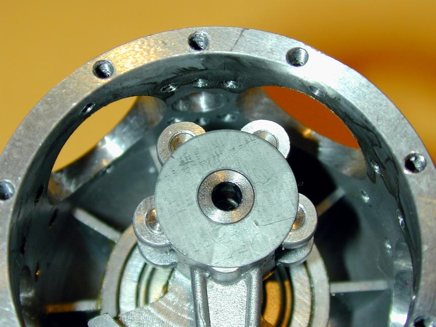
 Trial assembly time. Here we see the reason for the slip fit of the crank pin bushing. Commonly, radial crankcases are split around the centerline of the cylinder ring. This allows the master rod to be dropped onto the pin, then the other half of the case ring bolted up. As the Morton case is not split, the master rod needs to be fed through the #1 cylinder mount (that's the one on top of the engine), then angled to slip it over the crank pin. The only way to accomplish this is with an oversize hole--ie, without the bushing in place. The bushing can now be dropped into the gap. But once pushed home, there is no longer anywhere to grip it, so if it is tight in the rod, the engine can never be disassembled! To make matters worse, we'd really like the crank pin to rotate in the bushing, not the bushing in the rod. Well, it looks like it works. It's possible to slide the rod/bush back on the pin to the limit of the cylinder hole, then push the rod forward at an angle causing the rod to move on the bush enough to grip the bush for removal. Phew.
Link Rods
I know, I know... in the last section I was calling them "slave rods", now they're link rods. Some manuals even call them articulated rods which is probably the most accurate description. Whatever we want to name them, according to Bruce Satra, these were reputedly another weak link in the original Morton M5 (pun intended ;-). Due to the alloy they were cast in, they would fail at speeds in excess of 5000 rpm. The Vernal versions, Bruce says, should be good for 5500 rpm, if the rest of the bits can be coaxed that far.
 The rods have an "H" section. Each end takes a 1/8" pin and there is 0.841" between centers. First task was to clean up the casting gate and left-over sprue. In this picture, the 4 rods on the left are "before"; those on the right are "after". That gate is really tiny and I'm at a total loss to understand how the molten aluminum was persuaded to enter the cavity before it cooled--especially as there is no obvious way the trapped air was allowed to exit.

 This is another case of more time to make the jig than machine the parts. The clamp piece seen here is milled to be a close fit on the rod. The plate is counter bored a little deeper than the height of the bosses on the rods, so the clamp pulls the rod side firmly onto the plate. The counter bores are close fits on the bosses, so the rod is restrained in all directions. This plate is mounted on parallels in the mill vice, which has been clocked square to the table axis. It's now just a matter of: drill #32 followed by ream 0.125" (low speed, plenty of "suds"); traverse 0.841" on the DRO and repeat. Do this eight times. Done.
 Now a trial assembly of the articulated rods--damn, said I was going to call them link rods, didn't I? Well, once you watch them rock and rotate, "articulated" becomes a very apt description. To assemble, each rod is offered up through its cylinder mount and the link pin dropped in--it is impossible to fit the master rod to the crankpin with all link rods in place. After I'd played this game for a while, my mind belatedly turned to the problem of how the devil was I going to get this sucker disassembled?
Rocker Arms
The rocker arms of the Morton went through several changes owing to failures in service (yes, they ran Mortons in those days!) The Vernal investment castings appear to reflect the final evolution, matching a drawing from "MS Engineering". This company was actually two employees of the Burgess Battery Corporation who'd bought all the Morton inventory and dies from Burgess (who'd previously bought it from Morton). Looking at pictures of the various arms appearing in ECJ, the changes center around the valve end of the arm. My own Morton, SNO A511, shows noticible wear on this surface, suggesting periodic tappet adjustment and ultimately, rocker replacement would be necessary on operational engines.
 There are only three operations required on each rocker arm: clean up casting sprue with a fine file, ream for the pivot pin and tap for the tappet adjuster screw. Of these, reaming is the most critical as the reamed hole must be normal to the plane of the arm if it is to move freely in the close confines of the cylinder rocker posts. The 8-32 tapped hole also needs to be reasonably vertical for alignment with the push rod and seating of the lock nut (plus aesthetics). Looks like another jig is required.
 First, we take advantage of the fact that tapping size for 8-32 equals clearance size for 6-32 (this follows downwards for 4-40 and 2-56 as well). So a 6-32 cap head screw holds the arm to the jig while a milled shelf aligns it for reaming. The jig was milled so that tightening torque on the screw rotates it down onto the shelf (not away from it as would happen if the hole was on the other side). Reaming is then carried out under power with lots of suds to clear away the chips. The milled opening under the hole assists with removal of chips so they are not carried up through the reamed hole as the rotating reamer is withdrawn.
 The other side of the block carries a slot milled out with a 1/8" slot drill, cross drlled 1/8" for a pin that positions the arm for tapping. You can't see it, but there is a 4-40 set screw close to the open part of the slot that is adjusted so the arm rests level in the jig, assuring the tap will align correctly with the casting. Adjusting a set screw is much easier than trying to measure, mark and mill to some precise depth. Tapping is simple, if laborious and is carried out using a tap handle that is guided by a rod in the mill drill chuck. This is a commercial item made by "General", but shop modification of other tap handles is possible and most worthwhile.
 Here are a pair of Mortons worth of rocker arms (plus a couple of spares). Spare a thought for the machinists assembling Mortons who had to mindlessly carry out similar operations on thousands of arms. Guess that is what apprentices are for. The Morton drawings show screwdriver slotted 8-32 tappet adjusting screws. Motor Boy Bert Streigler suggested using socket head grub (set) screws instead, figuring they would look better, be easier to adjust and less trouble to make. Plus they are dirt cheap! The two arms in the top left of this photo show these in place. They will have to be anealed though before the spherical depression for the push rod can be reamed.
 Each tappet adjuster needs a locking nut. Either the standard size for 8-32 machine nuts today has grown from the 1940's, or Morton had special nuts made. Those on the original engine I have are 1/4" AF (across the flats) and about 3/32" thick. Commercial nuts today are much larger. I could have tapped out 6-32 nuts, but thought bright brass nuts would be aestheticly more pleasing. One nut nut manufacturing session comming up.
 First, the 1/4" AF brass hex stock is drilled, tapped, and nut blanks parted off. The depth I could tap gave only five nuts per pass using a 1/32" parting-off tool. Parting off leaves lots of burrs on the nut, so they need to be screwed to some kind of mandrel for finishing off. As this, and "nut thinning" in general, seem to be frequent operations in my shop, some time back I made a tool to assist. The basic idea came from George Thomas, writing in Model Engineer. It's just a length of 5/16" threaded rod with numerous screw on, knurled caps that are drilled to clearance size of common thread sizes and capture a screw, aligning it concentricly and axially with the lathe. These screws are considered to be "sacrificial" during the machining operations to face the nuts and relieve their edges. The nuts here get a 30 degree bevel on the top side and a circluar step about 0.012" high on the bottom side. Makes for a nice looking nut with a good seat for locking. They take a while to make though.
Valve Cage Nuts
 The valve cages are forced down onto their seats, forming a hopefully gas-tight seal, by externally threaded nuts. These are bored axially to clear the valve springs. The thread is 3/8", 32 TPI. I'm using the British Model Engineer series here because they are readily available in Oz, while UNF "specials" are not. Only difference is the threadform is 55 degrees, rather than 60. Running a 3/8" die down a piece of brass rod is not a fun task, unless the thread is partially cut first. So here, the thread is cut almost to size, then the die run down it by hand to complete the crests and troughs.
 After that, the stock can be drilled 7/32" as clearance size to the springs, and 1/8" sections parted off like sausages. Parting off will leave some attached swarf that can most easily be cleaned off by rubbing the nut on a fine warding file. All that remains is to cut a screwdriver slot in one face of the nut. This requires (you guessed it!) another jig. To keep all like things together, the jig that holds the rocker arms for machining has an unused face that can be pressed into service.
 A hole is drilled and tapped through to the chip clearance recess in the jig, then tapped 3/8-32. A solid, threaded stub of nut material gets a crude screwdriver slot hacksawed into it, then it is screwed into the hole as a back-stop for the nuts so that only 3/64" of nut protrudes. With the jig held in the mill vice and a 3/64" slitting saw positioned across the nut diameter, each nut is screwed in until it hits the depth stop. The saw is then traversed across the face. Always make cuts like these "climbing cuts" -- that is, cutter depth is being forced up the face being cut by the combination of feed and rotation. Going the other way is a sure recipie for disaster as the descending teeth will try to snatch the work and pull it into the cutter, which compounds the problem.
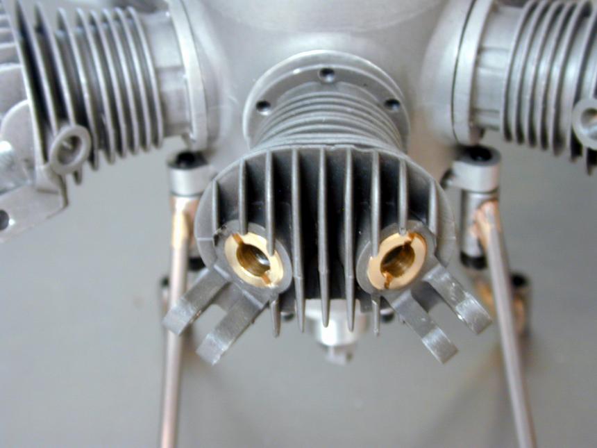 And here's a pair of nuts screwed home into the Vernal castings. The matt grey finish on Bruce's castings contrasts beautifully with the brass parts (IMHO). A special tool will have to be made to screw these little guys home, while the valve cage is held aligned with a rod inserted through the inlet/exhaust hones into the cage opening.
Valve Spring Caps
 More fiddly little parts! The valve spring caps are machined from 2024-T3 bar stock turned down to 0.220" to match the spring OD, plus a bit and drilled through to clear the 3/32" valve stems. As I'm using "C" clips to retain the caps, and these are parted off from 5/32" drill rod, the top gets a 0.016" recess counter bored in. Next, a 0.031" high head is left to a step cut to the spring ID, then another 0.031" to the part-off point. Repeat ad-nausium. Having now done all this, I'm feeling worried that they should have been made from steel. The Morton drawings call these out as 1025 steel--how much stress are they under, anyway?
Valve Cages
 Each Morton valve is housed in a bronze cage that doubles as valve seat, valve guide and the valve chamber connecting it to its inlet or exhaust pipe. Just like on full-size engines, in order to get a good seal, valves are lapped to their seats. But unlike full-size engines, the seats are not turned first--they are left "sharp" edged so the contact area will be very small. This arrangement depends on the seat area and the valve guide being closely concentric and that gives some production difficulties, given the nature of taper reamers and work-holding.
 Each valve requires four setups (though one is rather trivial). First, 3/8" bronze rod is chucked with minimal protrusion and turned down to 0.3125" for about 0.6". Next, a 0.046" long sholder, 0.250" in diameter is turned on the end. This will seat the cage in the head cavity. Now we are ready to do a lot of drill swapping: center drill #1, followed by #4, then #2 to 0.266" deep. Center drill #0 in the cavity, then drill #44 to 0.27" deep. The #2 hole forms the ridge of the valve seat. The #44 gets us within 0.010" of the 3/32" reamed guide hole, but we can't ream into the blind hole, so next step is...
 ...part off the blank. I find parting off bronze a nerve tingling experience. It's soft and a standard 3/32" blade needs to be kept very sharp, plus it wastes material. Much easier to just pop it under the band saw; then it's cut in seconds with only 1/32" lost. The end of the turned length is used to position the blade and was marked with odd-leg calipers set to give allowance for the cut width, plus less than 1/32" for facing back to final length. All blanks were produced in batch to this stage, ready for the next tooling setup.
 Each blank is now held in a collet to face the blank back to the finished size (0.547"), then to reduce the valve guide area to 0.155". This forms the step over which the valve spring will slip. Using a collet serves two purposes: first, it holds the cage as contrencicly as possible allowing the valve guide ID to be reamed 3/32" from the top, and second, it will not mark the finished surface like chuck jaws would. I found that this cut could be made fastest using the compound slide to get the precise 0.222" guide length. Any slight parallalism resulting from compound slide angle setting will not matter on this section of the part. The edges also need to be chamfered, so another tool in a quick-change holder is swapped in for this step.
 The last setup required on the valve cages is to hold them for cross-drilling a 3/16" hole which feeds into the cavity. This needs to register closely with the inlet and exhaust holes in the head casting, although some slight mismatch will not cause any particular problems.
![]()
