The Vivell Diesel Engines
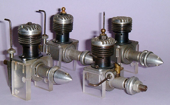
The Vivell project perfectly illustrates why the Motor Boys decided not to commercialize our work—for more about this, see the MBI Book page. When I started doing the CAD drawings for this one in 1997, I was living in Portland, OR. Three years later, I was back home in Brisbane and the Land Of Oz and the first MB Vivells are disturbing the peace at 11K+ rpm. The project has given us a lot of joy and if it took a while, who cares? This first picture shows the Vivell 09's in Tim's Model Museum collection. These are originals. Note there are fixed and variable compression variants on the right and left respectively, with a rear rotary valve glow at the rear and a front rotary at the, well, front...
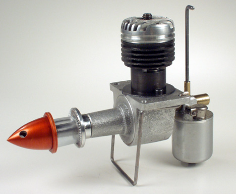
This pic shows a typical engine of nearly two years ago. Tank assemblies made by the RMBI. Crankcases and machining by the KMBI. Shafts, valves and head by Don Mac (Don's never done the Internet thing, so he's never been forced to adopt a "tag" signature). Spinners and prop drivers by the PMB/BMBI. At this point the OZMB was making cylinders in Wollongong, Australia. These would then go to Texas so GMA could internally grind a precise 0.0015" taper into them. On their return, they go back to the OZMB for him to hone the pistons to fit and marry them up with rods made by STAN (who seems to have avoided being tagged with a *MB line!). The engine in the picture is yours truly's.
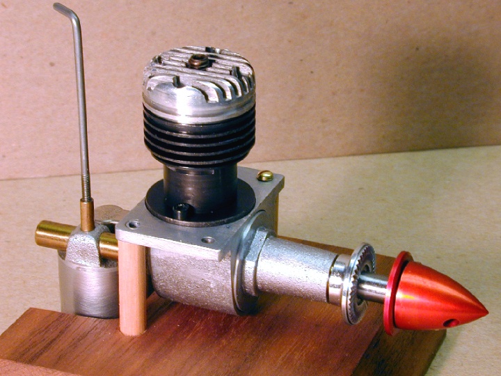
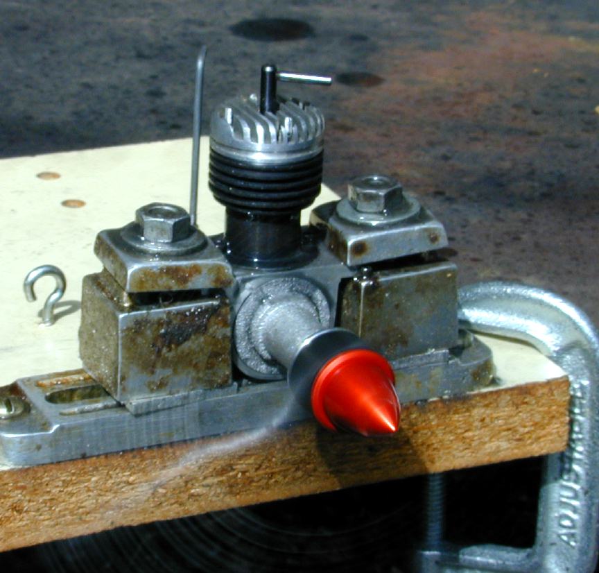
Now we arrive at June 2000 and the first completed Vivell 09 (Stan's) roars into life. He reports a lovely bark and 10,400 RPM on a Top Flight 8x4 wood. At this point his engine is not fully broken in, so it will definitely do better. If you look closely at the screw holding the cylinder down on this engines in comparison the rest, you'll notice a small difference. Stan blames answering the telephone in the middle of spotting the hole locations for having to go to a larger screw size. He has also added a little ferrule to his needle. I think it looks kinda neat, so I'll follow suit on mine.
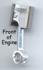
Now Stan knows a thing or two about small high performance diesels. Here's his piston and rod assembly. Apart from the outstanding finish on his connecting rod (and all the others, for that matter), note how he's relieved the front of the piston in the area of the transfer passage and provided a large lubrication home in the "big end".
The RMBI was next. At the time this photo was taken, Bert's engine had about 25 minutes on it and he reports it got better with each run. Now consider we are talking about an American 1949 design here. The contemporaries to this engine in the UK would be mostly side port designs and simply not in the same class. So why did this engine sink without trace? The collected MBI wisdom concludes that 1949 in the USA marked the introduction of the glow plug. That and the ready supply of methanol and nitro effectively sunk the diesel in the USA. Elsewhere, the lack of a ready methanol supply made the compression ignition engine king, though it was a while before designs caught up to this one, perhaps because of the "not invented here" syndrome.
And still they roll off from the production lines in the mighty machine shops of Kansas (well, Roger's basement, anyway). This one is George's made up from all the reject parts left over from his own. That's odd... mine is also supposed to be full of the KMBI's reject parts! Can't wait to see what his looks like!
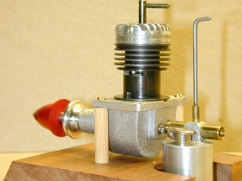
Here is Roger's engine with all the bits he deemed too good to give away. Note that Roger's (and mine) have a more conventional "Tommy Bar" type compression adjustment screw. The original 09 VC engines had a set screw adjustment exactly as seen on Stan, Bert and George's engines.
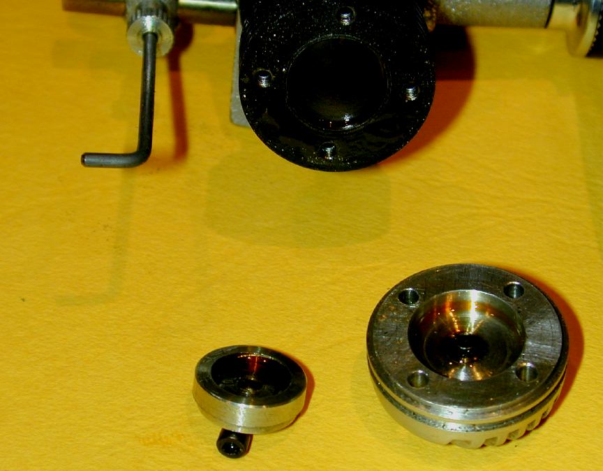
And finally, after a long gestation, my own Vivell 09 gets two holes drilled and tapped and a cunning two piece contra piston made—which is all the work I needed to do to complete it (forgetting making and anodizing all those spinners earlier). The two piece contra piston was a smart idea and deviation from the plans devised by Stan Pilgrim to achieve a good, gasket free head seal, while retaining the thermal tie between contra piston and head. Essentially, an aluminum contra piston rides in a flanged aluminum carrier that is a drop fit into the cylinder. An aluminum in steel press fit would lock up under heat due to the different expansion rates. With Stan's design, we don't care if the carrier locks up as it is stationary. The central moving part is aluminum in aluminum, so a tight sliding fit is retained as the engine heats up. Sounds mickymouse, but works great...
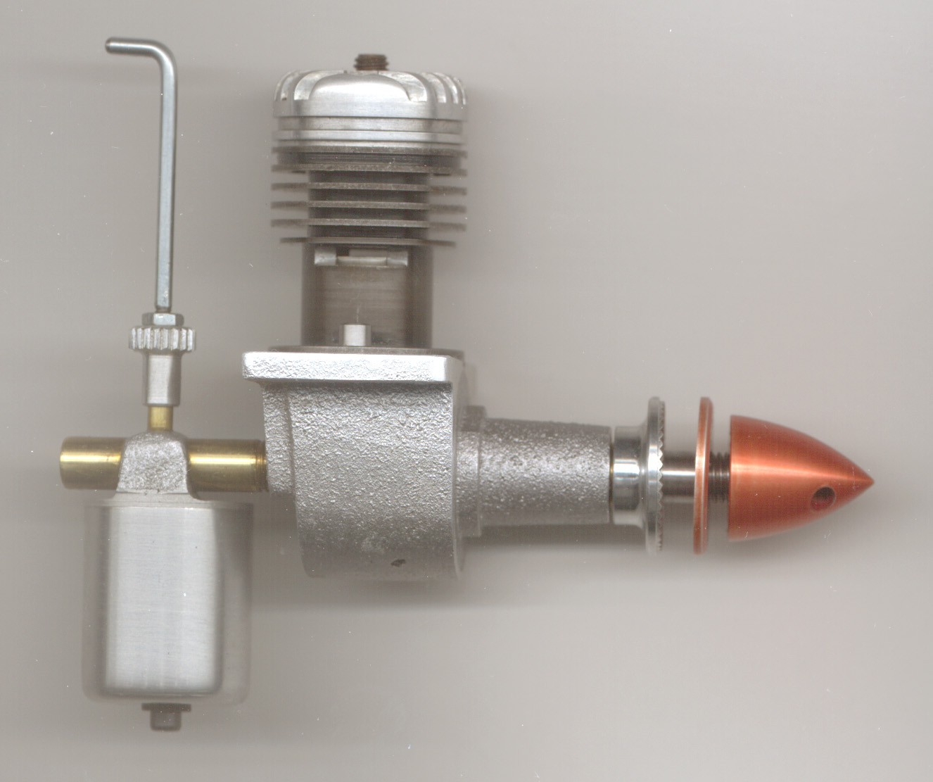
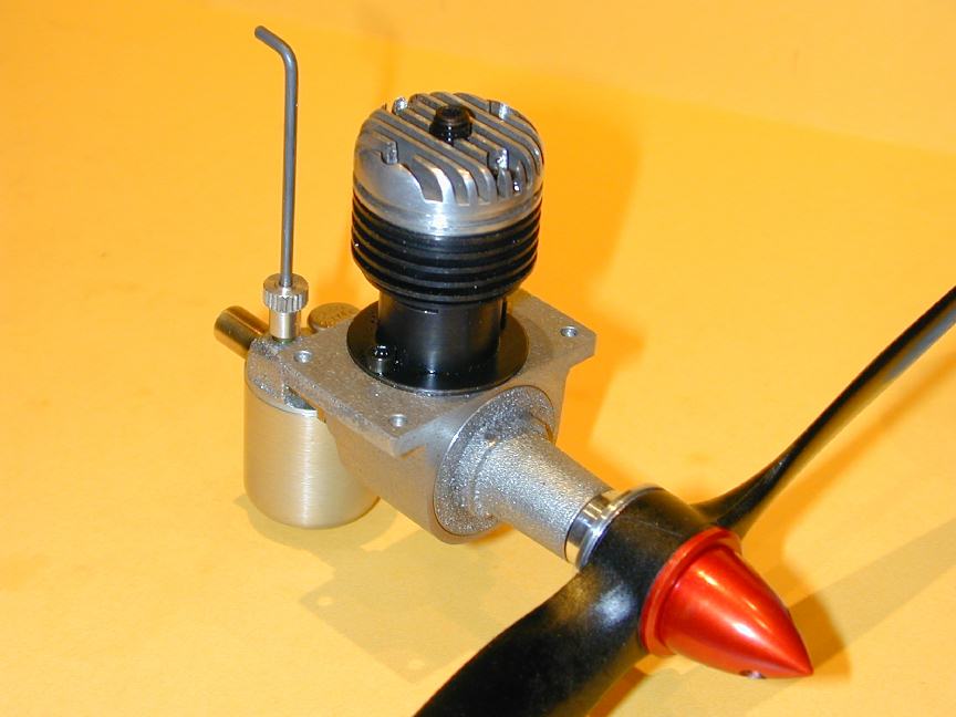
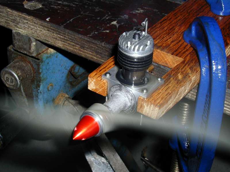
...as we see in this shot! The Vivell started very easily—a tribute to the makers of the moving bits, not me, and is seen here turning a 7-6 Master Airscrew plastic paint-stirrer at 8K rpm, still with a diesel "cackle" that indicates it can take more compression and give more in return. Remember, when these engines were being sold commercially in the USA, the equivalent engines in the UK would have been the ED Competition Special and "Penny Slot" (2cc, but side port), the Mills 1.3 and the 1.3 updraft Elfin. Performance wise, no comparison with the possible exception of the Elfin. But alas, the ready availability of methanol and nitromethane and an undeserved reputation as being "smelly" in the US made the "diesel" a poor alternate to the glow plug engine as a replacement for the spark ignition at that time and the Vivell and other US diesels faded to obscurity.

But wait! There's more... The EMBI has also finished his Vivell, complete with a two piece contra and a real neat needle valve. The rest of us took the simple route and made them from 2-56 Du-Bro pushrod ends. Nothing so pedestrian our for Ken—he started with 1/8" drill rod no less and turned it down to 8BA size (0.086") 1/8" at a time, smoothing as he went with a jewelers' needle file and extending the finished length into an 8BA bush in the tailstock!!! This would be noteworthy if done in mild steel, but to do it in drill rod goes above and beyond. All this to get a neat little knob on the end at the original 1/8" diameter a'la ED. They would have used a hollow mill that reduces and supports all in one operation to produce theirs, I'd guess.
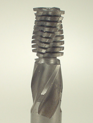
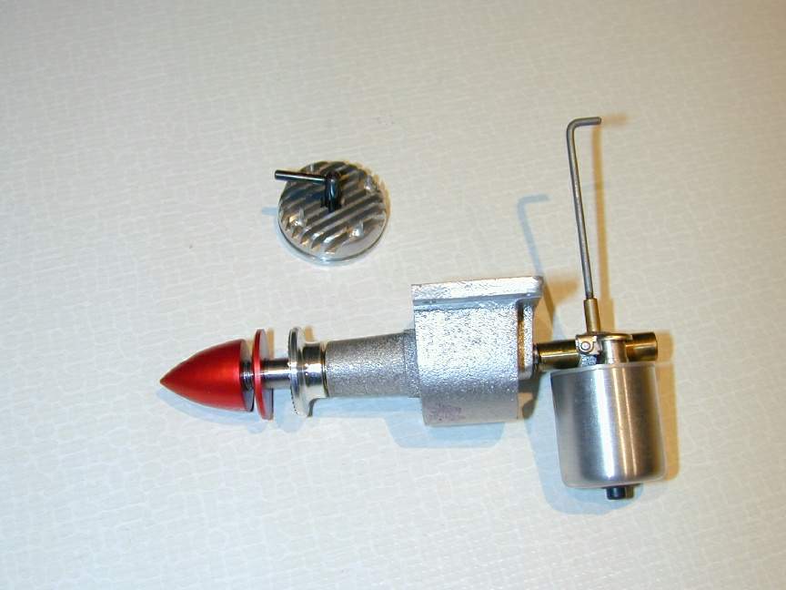
All the heads and shafts for the Vivells were made by Motor Boy Fellow, Don McClusky. Sadly, Don's health has forced him onto the inactive list, which is how you get to be a "Fellow" around here. The instrument of torture depicted in the photo is the tool Don made to cut the fins in the cylinder heads in a single pass. As you can see, it started life as a discarded end mill. Don cut those grooves by hand with a Dremal cutoff disk! I doubt if I could do better, or even as well with my QUORN T&C grinder. Bert rightly calls him a master of innovation.
Addendum: The Stan Pilgrim Two Piece Contra
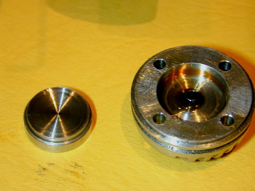 The piston at TDC (top dead center) comes quite close to the top of the liner bore. This is no problem for the glow variant, or the fixed compression diesel, but complicates life for the variable compression version. The VC head is taller than the FC one, but not much. The plans, drawn from an original engine are depict an aluminum contra piston. But an aluminum contra in a steel liner will quickly lock up because the aluminum will expand faster than the steel. The solution to this was devised by Motor Boy, Stan Pilgrim. His design change was to make an aluminum carrier for the aluminum contra. The carrier will expand hard against the liner, but the contra will still slide inside the carrier.
The carrier is a finger-press fit in the cylinder with a flange on top so that the bottom of the carrier is 0.030" away from the piston at TDC. The height of the flange is 0.002-0.005" higher than the recess in the cylinder head so that the cylinder head clamps the carrier down, sort of like a big aluminum gasket. The OD of the flange is a sliding fit inside the head recess.
The 0.030" gap is close to the correct running compression position, so if the actual CP is shorter than the overall carrier height, we will have enough range of adjustment for typical fuel mixes. The CP cannot be pushed out of the carrier during normal adjustment (ie, while being flicked) because the piston will hit it first (it could be if just wound down with the piston around BDC, but who would be silly enough to do that?)
Here's the dimensions I measured on mine:
Carrier:
- OD at flange: 0.567
- Height of flange: 0.121
- OD below flange: 0.512
- Height below flange: 0.055
- ID of carrier: 0.407
Contra Piston
- OD: 0.4075
- Height: 0.093
![]()
