Feeney Construction Log Page 4:
Crankcase
![]()
The Feeney crankcase, like many engines of this period, and some modern chain-saw two-strokes come to think of it, is split vertically. This allows the case to be assembled around the full-throw crank. The castings supplied are "green" sand cast, but appear to have been cast in a bonded sand like "petrobond", and have a reasonable smooth finish. The tow halves are aligned by a register that is machined onto the mating faces; female on the front, male on the rear. If this is machined to a close fit in the same set-up used to bore for the shaft, the front and rear shaft bearings will align perfectly. The challenge is aligning the castings for machining so that the exterior profiles show no great mismatch when mated together.
 The case is a rather irregular shape, and rather close to finished dimension, length-wise, so it requires careful setup in the 4-jaw independant chuck. We must first decide if we trust the patternmaker enough to use the cast faces as references. This is an eyeball operation where we jiggle the two parts together and see if the faces are relatively square, and if alignment should be attempted on the exterior, or interior dimensions. The answer is the faces are square, and external is the way to go. Now begins a dance with casting, chuck, scriber block and soft-headed mallet. In this photo, the point of the scriber is being used to check the OD at three 90 degree rotations between the case lugs, and to see that the face of the casting does not wobble more than a few thou as it is rotated. Tedious, but not difficult.
 The casting can now be faced back to external length and the female register formed on the inside. The forward shaft bearing hole is then drilled undersize and bored for a close running fir of the shaft (which is why we machined the shaft first). While it is not necessary to fully machine the interior of the case as I've done here, I found that the cast boss on the inside of the front wall was very ecentric in relation to the case axis, and as the space between his boss and the surrounding walls must clear the shaft counter-balance weight, it needed to be machined concentric with the shaft bore. Having done that, I gave the case a light interior skim as well.
The Feeney shaft runs mostly unbushed in the aluminium case, however the plans show a short bronze bush at the extreme front of the case. The recess for this bush could be machined in two ways: from the front with the case mounted on a true running mandrel, or blind, from the rear at the same setting as used to bore the shaft hole. This latter requires an unusual tool, and complicates measuiring, but I chose this way as simpler than the mandrel method. The tool seen above was touched to the bore ID and the cross-slide dial zeroed. It was then moved forward and used like a hook to locate the front extension of the case. The compound slide was then wound back by the length of the bushing, less 10 thou and an engineers clamp placed on the lathe bed behind the saddle as an indicator. The bush recess was then machined to the approximate OD required (to which the actual bearing will be made to match). Finally, with the tool at to OD setting, the final 10 thou was put on with the compound slide and the tool wound in to clean up the rear face of the recess. That takes longer to describe than do!
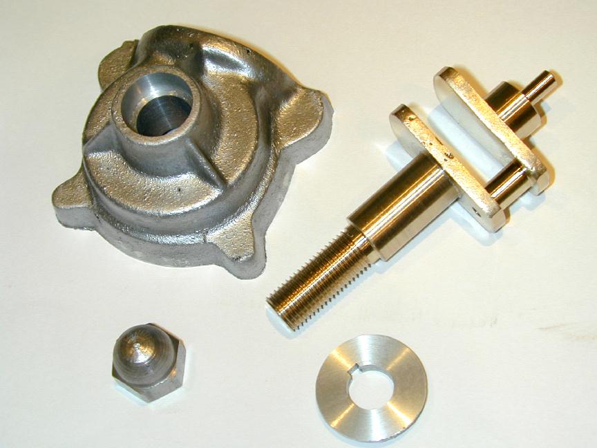
The Moment Of Truth! The finished case is removed from the chuck and we can see at last how close (or far off!) center the shaft bore has emerged from the front of the casting. I'm amazed. It's as close to perfect as anyone could wish. Must have been holding my mouth right, or something. For some unknown reason, I don't like the thought of a bronze shaft spinning in a bronze ushing, so the front bush will be transmuted to cast iron. This will not be made a press fit as that would close up the bore, and lapping it out would not be fun. The solution is to glue it in with an anerobic adhesive (like Locktite (tm)).
 Here's the bush just prior to fixing in place. It's been turned to be a close sliding fit in the recess, so close that it would probably wipe all the Locktite off as it was pushed in. To accomodate the adhesive, I've machined a 0.001" deep grove around the middle of the bush. You can just see it if you squint closely at the pic. This will form a resavoir for the anerobic adhesive while the bush fit takes care of alignment. Proof of the pud' is that the bush was bored to be a close running fit on the shaft, as it is in the case. After final insertion, the shaft slid right in with no hesitiation whatsoever. I'm not surprised. This trick of machining recesses from the back is used to open crankcases to accept front ball races, though measuring for a press fit of the front race must be tricky.
 Setup and machining for the rear case half is similar, except the shaft bore is blind. Before mounting the case, careful measurement is made to see how much material needs to be faced back from the casting, and to make sure that machining that blind bore to size will not make the case paper thin at the rear. I did have to finesse things here a little, but not significantly. Again, the scriber block point is uesd to get the best possible radial alignment at the points between the case lugs, assuring that our halves will at least register at 3 points.
 Here we are, machining complete, ready to remove. The male register can clearly be seen. This has been machined very carefully to be a close, working fit in the front half (ie, it enters without force, but the two parts will stay together until pulled apart). This is essential to get the shaft bores into alignment. I've not bothered to fully machine out all the interior of the case rear, just the bit around where the rear crankshaft cheek will rotate.
 One of the most crucial machining steps in any engine is ensuring the the cylinder bore is at right angles to the shaft bore. With a case like the Feeney, this is a bit difficult. My solution was to machine a close fitting mandrel for the shaft that is used first to drill and tap for the case bolts, then to align the case for machining the cylinder seat. This shot shows the setup used for the facing operation (looks like I forgot to photograph the screw drilling and tapping step). Don't forget to measure the diameter of the mandrel before mounting the case (it should be the same, or maybe half a thou larger than the shaft OD). It's alos important to aligh the axis of the mandrel with the mill table—which is why I chose to do all this on a faceplate screwed to the rotary table.
A plunder type DTI is then used to find the high point of the mandrel. That gives us one coordinate for the cylinder bore. The other is found by finding the mid-point between the two machined bosses inside the case. A boring head is then used to open out the case for the cylinder spiggot. I'd toyed with doing all this work on the lathe. Machining would have been easier, but it was much easier to align things on the mill, so the mill won. I found that I needed to go out larger than the plans to clean up the "as-cast" bore ID; 0.030" larger! This was perhaps a mistake, though not a bad one as we'll see later when the cylinder is machined.
The holes for the tappet guides and crankcase breather tube are located relative to the cylinder axis, so they can also be drilled at this setup. I regret now not taking the time to make a drilling guide for the cylinder mounting bolts and drilling and tapping them at this setup too. Instead, I decided to "spot" them from the cylinder later. This will be a tricky operation and the time to make a guide thak could be used for case and cylinder would have been an overall time-saver. The shor here shows the case halves, separated, following removal from the mandrel setup.
Before pulling down this setup, the case is rotated 180 degrees and the mill y axis adjusted to recenter over the camshaft axis. The casting is them faced and trepanned to provide a seat and clearence for the point assembly. At the same setting, a blind hole is drilled and tapped 4-40 for the screw that will secure a spring steel finger whose function is to hold the point assembly casting in place and apply sufficient friction for advance/retard action. One more use for this setup: rotate the case 90 degrees to bottoms-up position, and the hole for the sump drain screw plug can be drilled and tapped.
It's gotta be fixed, but I still want to avoid grinding that special rebating tool (having had them break disasteriously before), so the plan is:
Back to Feeney Journal front page 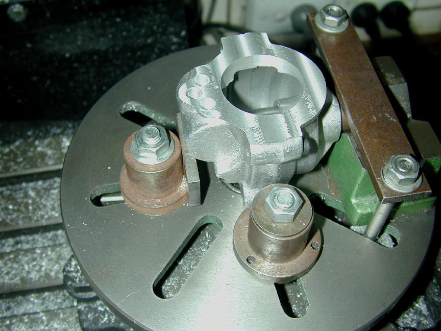 The case, securely screwed together, is slid onto the mandrel, and secured from any movement by wsdging blocks. The set-up here, while secure, took a long time to get right. If I were doing it over, I'd use posts drilled for long bolts that could be tightened positively against protective pads on the case exterior. I think it would heve been quicker in the long run, and I'd have them for the next time I'm faced with a problem like this one. Anyway, having got it all secure, the cylinder mounting flange is faced down to "deck" hight by measuring between the machined face, and the top of the mandrel—which is precise, known diameter.

 This over-exposed shot shows the case with crank posed for one of those trial-fits which are really excuses to admire our own craftsmanship (don't worry, all model engineers indulge this practice, frequently carrying the bits around the house with them for hours afterwards). The next operation will be to bore out the cavity for the skew gear and cam assembly (the thing that started this whole obsession!)
 This is a critical operation. The axis for the cam assembly must be located precisely in two dimensions to achieve the correct mesh of the gears. Fortunately, that's not too difficuly. First, the mandrel used earlier is cut down, faced and tapped so it can act as a stub to align the rear case against an angle plate. The plate is squared with the mill axis and an edge-finder used to locate the reference plane for one of the crucial dimensions. The edge-finder is then used against the mandrel stub to establish the axis of the mandrel as the other reference.
 With the rear case half slid over the mandrel, it is aligned so the cylinder seat is vertical and secured to the jig. The G clamps are a bit crude, but they worked well enough. It's now a simple matter to precisely locate the axis of the cam shaft, vertically from the mandrel axis, and rearwards from the case centerline—adjusting for the case register which needs to be measured before clamping up. I forgot, and had to remove the case to double check this measurement. First, the case is drilled thru undersize for the shaft bushing, then blind bored to form the camshaft cavity. This is simply opened out to final depth with a slot-drill, then finished to size with the adjustable boring head. With this done, the hole for the camshaft bush is reamed to size.
 Another screw plug is drilled and tapped in the front face of the front case half (shown being tapped in the photo here with a nice tapping accessory that I don't often get a chance to use due to space limitations under the mill quill). This one is arranged so that with the engine horizontal, it can be removed and oil syringed in until is begins to overflow. The oil level will the be such that the crankshaft counter-weight is just brushing the oil surface. When (if!) the engine is running, the spinning shaft and vibration will fling oil all over the place and a mist will develop that will lubricate everything except the rocker arm pivots.
 Another Moment Of Truth. After machining and fitting the bronze bush for the camshaft in the case, the driver gear is pressed onto the crankshaft with a spacer whose width provides the axial location and whose diameter—smaller than the shaft—provides clearence for the driven gear. The driven gear was then popped onto a stub of 1/4" drill rod—and—miracle of miracles—it all works. The mesh is correct in two axies and endless hours of mindless, unproductive fun ensue spinning the shaft and watching those gears go round.
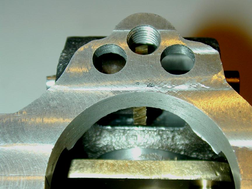 This shot shows the way the cam cavity breaks through into the main case cavity, allowing the gears, cams, and tappets to be lubricated by splash and oil mist from the wet sump. The passage also provides the connection that allows the crankcase breather tube positioned between the tappet guides to vent corrosive gasses from the case, while limiting oil loss—unless the engine is operated for any significant period at negative G's (joke). The positions are per the plan, but if I was doing over, I'd move the breather hole aft a thirty-second or so to give more spacing from the tappet guide holes.
Postscript 1: Assembly problem
 The way in which the timer is mounted as shown on the Feeney drawings required a narrow recessed track be rebated into the faced off recess on the side of the rear casting. This would require a very tall, thin, lightly curved and very delicate tool to be ground. I cheated and paid the price when the trial fit of the timer was made: my revised mounting worked, but the timer protruded so much that it would be impossible to fit the engine mount and nut to the case screw that pokes out located just in front of the timer. As they say in the classics: bugger.
 To line up the casting on the camshaft bore, a stub of 1/4" drill rod is center drilled on each end in a collet. The case is slid onto the stub and suspended between centers allowing an angle plate to be bolted to the faceplate using the case face for alignment (with a business card under the case to protect the edge). A single clamp holds everything in place adequately for light cuts (after this shot was taken, a counterbalancing weight was bolted to the other side of the faceplate).
 The case can now be counter bored (or faced, whatever) down to the required depth using a left hand tool to form the outside half and a right hand tool to finish up to the pressed-in camshaft bushing. The bushing will be used to locate a thin disk of aluminium that will form the bearing that positions the timer body.
 The disk is turned to be a close working fit inside the timer body, drilled to be a press fit over the cam shaft bushing, and parted off 1/32" thick. Before parting off, a light rebate 0.001" deep is made from the center to within 1/16" of the edge. This forms a space that can be filled with Lockitie as a bit of added insurance against the disk ever working free after it is pressed onto the protruding camshaft bearing stub.
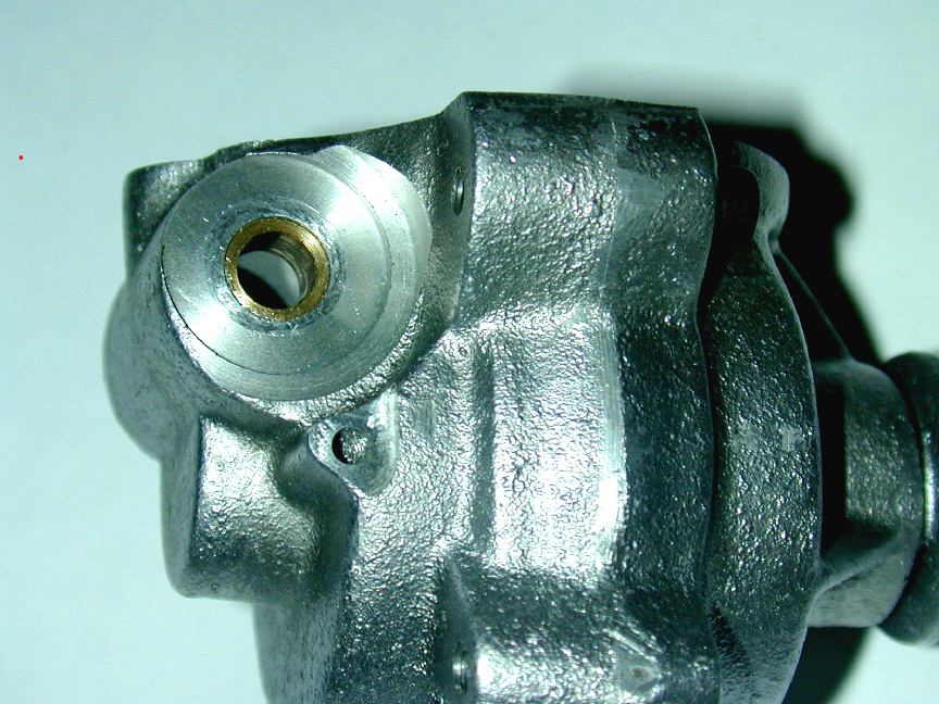
 All fixed! The timer rotates smoothly on the "rebated" track, held in place by the light spring clip that also provides anti-rotation friction. There's now sufficient room to get the engine mount, washer and nut onto the long screw that secures the front case to the rear. It would be a good idea to clamp the rear case down to the mill table and face the rear of all the lug protrusions flat and to the same height to provide a uniform surface for the motor mount. Somehow, I don't think the real Feeney's never bothered with that, so it will be a deviation, but a good, practical one.
![]()