Editorial
Hopefully, you are not as amazed as I am that 2007 is almost half over. Here in the southern latitudes, June marks the start of official winter. In years past, I would have a stock of firewood piled around the letterbox and have already pulled out the winter woollies. But not this year. As I drive out to campus at 7am in the morning, the dashboard tells me the temperature is a balmy 20°C. The top of the car remains "down" and I'm still comfortably wearing vendor supplied t-shirts. Maybe this does not indicate Global Warming, but it is for sure the first time conditions have been like this at this time of the year in my memory.

However, I'm happy to say that it did actually rain here last month—a whole 12mm (half and inch in the old money), but that's more than we've seen in the last three months, so it's gotta be good. The experts are saying conditions in the Indian Ocean indicate we might expect normal rainfall during winter. That won't fix Brisbane's Level Five water restrictions problem, but it means we won't be asked to further reduce our water usage either (currently, we are being asked to average no more than 140 litres per person, per day). Just in case you are wondering what that little observation has to do with the picture, the answer is "not a lot". It's just there to cheer up an otherwise depressing paragraph  .
.
Now I hope you are all checking the Update Index in the Site Map that shows files added and changed since last month. The list this month is rather large (75 files) and I feel moved to offer an explanation. First, there are a lot of new pages. Then there are the fixes and changes that have been applied to others to correct misinformation, or add new facts that have come to light. Finally, there is a significant group of pages that have undergone cosmetic changes only. The Kestrel and Kinglet fall in this category. In fact, these pages are generated from data files by a Perl script because writing them by hand would be just too boring for words, not to mention potentially error-prone, given all the cross-linking involved. The cosmetic changes came about as a result of the work I did on the Seagull and Seamew. This effort resulted in nicer looking "Next" and "Previous" icons, so the other pages were regenerated to incorporate the new, neater appearance. I develop and test using the Firefox browser. Website stats shows that Microsoft IE still has 70% of the market and the navigation icons don't quite come out as well under IE. Too bad.
As usual, there's a lot of new stuff this month, and a lot I wanted to include before time beat me. For instance, last month's Tech Tip on model engine fuels sparked some heated debate on a popular discussion forum. It also motivated a reader to email in some very good and well researched questions on the subject of paraffin and kero. Still, that gives us something to look forward to next month. Now on to business..
Morton M5

Seems to me that Bruce Satra has done more to develop the Morton M5 radial than did its designer, Glen Morton. Up until now, the "current last word" for the M5 has been the CAD plans published in Model Engine Builder. You could argue that they still are, although they need a tiny update to accommodate Bruce's latest improvement. Bruce has been gradually addressing the factors that limit the "never exceed" RPM of the engine. First, he beefed up the rocker arms. Next the master and slave rod alloy was changed. These changes moved the max speed from 4,000 to 5,500 RPM. Addition of an extra ball race support for the slave shaft raised this again, but the extra speed resulted in increased stress on the rockers again, so Bruce arrived at the ultimate rocker solution seen here: rockers cast from 4140 steel! As steel on steel is not a great idea for pivots that receive only accidental lubrication, Bruce suggests that the 4140 rockers be reamed 5/32" so that short lengths of 1/8" inside diameter K&S brass tube can be Loctited in as a bushing. This is the solution I hit on for the steel Cirrus rockers. Bruce knows of one M5 with steel rockers that is turning over 6,000 RPM and is regularly flown in a sport R/C model.
Among the other parts in the photo are pistons modified to give 9:1 compression for glow ignition, higher rate springs, pressed steel valve caps, and special steel washers that sit on the crankpin either side of the master rod to act as retainers for the fully floating slave rod pins. The original Morton design used pins that screwed into one side of the master rod. These were prone to working loose, resulting in a sudden stop with accompanying expensive noises. Prices and contact details can be found on the Vernal Engineering web site.
Morton M4

Just having a Large Library is not enough. You need a Large Index, or Large Memory to go with it. I'm going to claim failure on both counts as a reader emailed to tell me that the American Modeler Annual for 1965 contained yet another example of the elusive M42, four cylinder, in-line, side-port, four-stroke engine. The Library had a copy, but if I'd ever seen that page, I'd totally forgotten about it. The article, by well known collector RE "Doc" Nichol, describes how the Morton factory was including a copy of the (only) M42 drawing sheet with M5 plan orders. This sparked some talented builders to develop their examples from very scant data. Re-visit the M42 page for an update.
A New Gallery Page

The Engine Gallery receives a brand new Gallery Page this month, the previous one having reached about the size limit I like to keep these down to. On it you'll find out just what the devil the thing you are looking at here is, plus some other neat builders' work. The Les Stone Tribute Page has also got an update showing Les' latest: a three cylinder Anzani "fan" engine, which probably qualifies as a radial in the same way that a V twin is a radial.
Bring Out Your Finish

The UPT is not quite finished, but it is closer. This month, the process of bringing out the finish on cast iron is demystified—or obfuscated, depending on your point of view. I'm not all that happy with the color (Ford engine block blue) or with the gloss of the finish delivered by the el-cheapo spray can used, so it will all come off and we'll get a good can of workshop green enamel Real Soon Now. Click the photo or go to the UPT Home Page tor details on this tiresome, messy, boring, but satisfying process.
Model Engineer Plans On-line

If you don't live in the UK and have ever tried to buy a plan from the Model Engineer plan service, I feel for you. Through a succession of owners, servicing overseas orders always seems to have been under control of the Director of Sales Prevention. This *may* have been addressed. All of the ME plans, including the PE25 Seagull plan, can now be ordered over the Internet through MyHobbyStore dot com. The site lists 43 IC engine plans ranging in price and complexity from the MM251 Weaver for £5.95, up to £34.95 for PE33, the Blackmore BR2 rotary on 7 sheets. The site appears to be still under construction as the plans have provision for a "Star Rating" to indicate project complexity, but so far, no stars. Still it's good to see an effort being made to make all the old plans, including the Aeromodeller plans, available to electronic shoppers.
This made me wonder if the X Plans website might be defunct, but no—they seem to be alive and well. Presumably, the MyHobbyStore site does not provide plans from the old X-list, so between the two of them, every plan Aeromodeller, Model Aircraft, Model Maker, Model Engineer, etc has ever published can be obtained over the 'net (sorry, you have to pay though).
Moteurs MA New Website

Some time back, I introduced the unique engine designs of the talented French Canadian machinist, Michel Arseneau. Michel has had to move his web site to a new URL: http://motorma.netentreprise.ca/. The Model Engine News Link Page has been adjusted accordingly and if you bookmarked it, please take a moment to update your link. Michel was kind enough to send be an unfinished set of parts for his 60 sized, horizontal-piston, Aero 35-like engine, seen pictured here. With the exception of the cooling fin cuts, these were produced by CNC—a task at which Michel is a obviously a master as the fit and detail is just perfect. Now all I need is the time to complete the assembly. Incidentally, unlike the Aero which was loop scavenged with a front (side?) rotary valve inlet, Michel's 60 size engine is Schnuerle ported with an automatic inlet valve.
Of Seagulls and EDMs

In exchange for burning out some broken 6BA screws from an early mark Frog 500 crankcase using the EDM built last year, I now have a partly machined ETW Seagull to join it's companions under the bench. In actual fact, this is one project I'm going to give serious thought as to how the problems the original builder caused himself can be corrected so it can be completed to running state—mostly because it's a two cylinder, side-valve four-stroke and I keep hearing how docile and quiet this type of engine is. Click the link, or the picture to visit the new Seagull page for more details of this half-century old design.
 Incidentally, it turns out that removing broken screws is a lot harder than removing broken taps. With a tap, you can EDM away the "core" and the fluted cutting edges just fall out. To remove a broken screw, one needs ideally to create a cavity into which an Allen key might be inserted to unscrew the offending piece. But with the Frog's 6BA screws (about the same size as a 4-40), there is just not enough meat for this—not to mention that the screws broke in the first place because they were well and truly corroded in place! Burning through 5/8" of screw almost to the tapping drill size was easy enough, but the residue just refused to budge. Finally, the holes had to be cleared with a 6BA tap, trying very hard to pick up the original thread start. It worked, though the screws are looser in the thread than I'd like. I need a better approach and more practice.
More Buzz on the Hornet

Last month's review of the ED Hornet attracted a most informative email on the serial numbering scheme used by ED for all their engines up to 1963. Click on the ED Competition Special photo to go to the Hornet page, or or click here for the ED serial numbering expose. The email also questions my identification of the piston as hardened steel rather than the more usual cast-iron. Well, I question it too, and having a Hornet in for repair due to the usual lack of compression, I will be taking a skim over the piston crown to see what the swarf looks like. There may be crow on the menu next month...
New Books and Magazines This Month

Model Engineer, that most venerable and respected of English magazines, underwent a format change with issue #4293, volume 198, dated 16 Feb-1 March 2007 (yes, that's old news, but my copy comes via the local newsagent and a very slow boat). This is not the end of life as we know it as ME has undergone a *lot* of layout, format, and even content changes over its long, long history. I mention this seemingly insignificant change because it represents yet another shot in the Font War that has been hotting up in recent years.
 This small sample—which hopefully will not get me shot for copyright infringement—shows the old and new depicted to the same resolution and scale. The most obvious difference is the change to a larger, sans-serif font. This decision appears to fly in the face of a significant body of research which has concluded that humans—a classification that describes most model engineers—find serif fonts easier to read on a printed page, but prefer sans-serif fonts on video terminal screens. I'm inclined to agree (notice the sans-serif font chosen for the text you are reading as opposed to older pages of this site such as The Anodizing How-To, formatted before I got serious about such things). It will be interesting to see how the readership responds to this bold experiment and one that I shall watch keenly. Overall, I applaud the editor's decision to respond actively to the changing times and reader survey results (the 3D drop shadow on the Masthead is new, too ).
-oOo-

Even though my ME copy arrives by pedigree racing snail, I get the sister publication, Model Engineers' Workshop, delivered by an aluminum eagle. Here is issue #125 of May 2007, hot of the press. It gets a mention because of an article by Alan Johnson called "A New Life for Old Model Aircraft Engines". Alan describes the process he has derived for restoring lost compression by growing cast-iron pistons (as described here in the Taplin Twin Prototype page and others), then lapping cylinder and piston. This is worth mention because the expanding cylinder lap depicted is one I've not seen before.
The author mentions reading some (unreferenced) articles on fitting pistons and liners and notes that not all of them agreed on the process involved. In the time honored manner, he conducted experiments into those he though the most workable, finally arriving at a variation that uses a lot less metal than I invest/waste when making a cylinder lap (hone, whatever...)
 This drawing shows the idea. The lap itself is a relatively short lump of aluminum bar that is turned to a close fit in the bore. It is the bored through and blind drilled and tapped—sort of like for a wrist pin. Finally it is slit to facilitate expansion. This is effected by a threaded grub screw that also provides mounting for the stop-collar equipped shaft. The shallow grooves on the diameter are intended to assist lubrication and to carry away metal particles. The way the lap is mounted, like a piston, will accommodate some degree of movement, which is good as the photos show the lap shank held in a variable speed electric drill while the liner is clamped between contoured wooden blocks in the bench vice!
Now I've not tried this arrangement, but it appears practical. The adjustment arrangement should result in relatively uniform expansion, meaning it will hone a parallel bore. The author confirms this is the case, and goes on to describe an involved process for using it to introduce a taper, this being important in order to give that nice piston "nip" at TDC. The sort of lap I favor uses a lot more material in construction, but provides the taper for free (see How to Make and Use Cylinder Hones). Finally, it comes down to what you have found works for you.
The rest of the article describes a variation on the split piston lap and the process involved in compression restoration. The only issue I would take with the process is a suggestion that "...if very much material has been removed you may have to case harden the liner again before finishing the lapping process." I would most strongly suggest you don't try this as the chance of quench-induced distortion is just too great. That aside, overall this is an interesting new slant on a process that is a perennial mystery to beginners, but one that once mastered, is not all that difficult.
Engine Of The Month: Graupner-OS Wankel and Z&H Cirrus

Time pressures this month prevented me researching and writing up an engine, so I've fallen back on the David Jansen book for a suitable subject, ie, one for which I can replace the photocopy quality black and white images with nice color ones. The subject chosen is the .30 cuin "rotary" Graupner-OS Wankle. When this engine first came out in the 70's, engine users far outnumbered engine collectors. I remember examining one in the local model store and asking myself why on earth anyone would buy an expensive OS Wankel when a cheaper, lighter, more powerful OS .30 was available? My, how times and tastes change. Click on the thumbnail photo to read the review.
As I was updating the Jansen Index page, the word Cirrus caught my eye. Turning to that page confirmed that yes, this is the actual limited production run of engines that preceded the publication of the engine for home construction in SIC. As I read the review, another familiar name appeared and another piece of the puzzle dropped into place. Even though I don't have an actual D&B, Z&H, whatever, Cirrus to photograph, this extra information was too good not to share, so this month, we have a second Jensen review. Visit the Jansen Cirrus Review page for the original text, plus my footnote observations.
Tech Tip of the Month
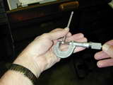
There are times when a third hand would be a real handy thing to have (feel free to groan at the unintentional pun). One of those times is when trying to accurately "mike" a bore gauge. Unless the rounded ends of the telescoping T arms are in line with the axis of the micrometer anvils, the reading will be wrong. Sure, the error will be small, but as this operation is used to measure cylinder bores on engines where tenths of a thou are significant, errors are unacceptable. The solution is a stand to hold the micrometer leaving one hand free to align the gauge while the other turns the screw. This month's Tech Tip provides the basic concept for a simple micrometer bench stand, and shows how two innovative model engineers adapted the concept to materials on hand.
 Morton M5
 Editorial


