Editorial
 This month's issue has turned into a bit of a monster, which is rather appropriate given that it's being posted on October 31. Things are heating up here, downunder, rather fiercely. Soon it will be too hot to spend time in the shop, or do much anything except sit in front of the keyboard. Ahh well, them's the breaks. Quite a lot of stuff again this month; shop action, product announcements, real cool pics from readers, an update on the Glow Chief Restoration (pictured here), two useless tech-tips from moi, the whole 8.2296 meters.
There's been a minor re-organization of the Gallery page. It got quite a lot of new pictures added this month courtesy of Bob Palfrey and Kevin Wils. During the update, I noticed the page was getting noticeably slow to load across the network—heaven knows what it was like on slow speed dial-up connections. So it's been split into multiple "pages". With luck, this has not broken any links directly, and any which referenced the page itself will now go to a Gallery index page, of sorts...
Most astounding of all is the hit counter result for the past 4 weeks. When the October Model Engine News page was put up, the hit counter stood at 77338. As I link this page into the framework, it's risen to 83586. An astonishing and record breaking 6248 hits! Or maybe those pesky spam generating robot crawlers have been unusually busy this month—my In Box sure looks like it—who knows? Click on the hit counter to see the stats generated by Bravenet and judge for yourself. Now on to business...
Syndey Collecto
 First, a community announcement. A mail-out from David Owen on behalf of the Australian MECA chapter says that SSME, REMAC, and MECA members will be holding a Collecto on Sunday November 9, 2003. The event will run from 10am to 3pm at the Sydney Society of Model Engineers Inc, 869 Luddenham Road, Luddenham, NSW 2745 (and now you know what at least one of the alphabet soup mnemonics means). The Collecto (MECA-talk for "collect-together") is open to members, non-members, friends, enemies, non-human life forms, anything with some interest in model engines. If you want to attend and need more details, contact David by phone: +61 2-4227-2699, Fax: +61 2-4227-2975, sail-mail: PO Box 1739, Wollongong NSW 2500, or click on his name to send an email. I probably should mention that the map was generated by WhereIs.
It's the AHC, All Over Again
 The past month has seen the creation of three more AHC diesels, two of which have been my implementation of Bert Streigler's Red Rover rear rotary valve variant. I've tried a number of innovations in the process and will write them up in the AHC Project section when I reach conclusions. Ken Croft has been driven in-doors by the approaching English winter and is also making an AHC with some innovations of his own. This too will be reported on in the fullness of time. Watch—as they say—This Space.
Chenery Anzani
 An email last month from Discovery Channel (Europe) led to a little search for the snail-mail address of engine designer and builder, Les Chenery (who now appears in the Suppliers Page). The search also uncovered a couple of pictures showing an example of the Anzani three cylinder "Y" radial built by Mr Mick Cherry. This is just one of Les' designs that has been serialized by Model Engineer in past years. The construction series started in issue 4022, dated 2-5 August 1996, and continued for the next eight even-numbered editions. Try TEE and Wise Owl for back issues. The "Y" engine is distinct from the other Anzani three cylinder Eventail, or "fan" engine that powered the cross-channel Bleriot monoplane. The Aircraft Engine Historical Society has an interesting piece on air-cooled aircraft engine cylinders by George Genevro that recounts some background of these engines (I believe that is the same George Genevro who designed the Titan .60 glow engine—featured as a construction series by Roger Schroeder in ECJ several years back). Other Chenery designs include a 1:5 scale Gnome 9 cylinder rotary (featured in ME starting with issue #4161), the DH Gypsy in-line 4, a non-scale 15cc V-Twin four-stroke, and more lately, the horizontally opposed two cylinder four-stroke that powered the world's ugliest airplane. Alas, he has no on-line presence that I'm aware of.
Woking Adds Gnome 9 to IC Kit Line
One discovery leads to another. I knew that Woking Precision had plans and castings for the Chenery 15cc Aero-V available, and while capturing the link to include in the Chenery Anzani piece above, I happened to notice that Woking's range has expanded to include CAD plans and castings for a Gnome 9 cylinder rotary. This is a 40% scale model (twice the size of the Chenery 20% scale model), giving a stated capacity of a whopping 500cc! Stand back, stand well back...
An Innovative Use of eBay
 A reader alerted me to an off-beat, but on-topic, use of the eBay auction site in the past month. Seems as someone (who goes under the eBay name of tomdayle.cross) is using eBay's auction listing as what I'd term a Classified Adds service. It's "on-topic" because the offered item is a video tape on model engine construction. As the auctions (there were three running last I looked) will have well and truly ended by the time you read this, I suggest you search on the seller's name. I'm sure he'll have new postings available, since his supply of the "auction item" is effectively endless. All he has to do while punters keep buying, is keep making new postings. I've no idea of the quality of the tape content. He (I'm assuming a "he"
  ) claims to present machining techniques for a Lindburg Hornet—presumably from Roger Schroeder's kit, and a 1937 Husky as pictured here—possibly an Art DeKalb kit, but there may be others. So, ten points for innovation, but certainly not something to get in a bidding war over.
New Books and Magazines This Month
 A lean month for new stuff, so I'll mention a slim volume written by the late, great ET Westbury on the subject of Grinding, Lapping and Honing (ISBN 0 905100 68 9). This work was first published in 1950, and was reprinted by TEE Publishing in 1987. The title page says the 78 page booklet describes "The application of abrasive processes to finishing surfaces to a high degree of precision, with descriptions of machines from the operator's viewpoint." True enough, 'though many of the descriptions are more tantalizing than informative.
Seven chapters cover an introduction to the topic, principles of abrasive processes, types of grinding machines, tool and cutter grinders, cylindrical grinders, surface grinders, and lapping and honing. Illustrations show industrial machines from the period as they might have appeared in a catalogue—which is to say, perhaps enticing to someone who knows what he's looking (she would have no idea), but perplexing to someone who is not familiar with the equipment. As most of us amateur machinists are going to fall in this latter category, the view of some device covered in hand-wheels, spokes, motors and slides called a "Churchill Universal Grinding Machine" is, as said before, more tantalizing than informative. Never the less, Westbury does manage to convey the tasks the machines were intended to perform, at least at a high level. The process of "centerless cylindrical grinding" (often touted by engine manufacturers as how their pistons are made) was always a mystery to me. After reading Westbury's description, I can see how such a machine might work, although I'll confess that I'm surprised it is able to achieve the desired end result, let alone with "tenths" precision!
The last chapter dealing with lapping and honing, although again describing some machines beyond the pocket (and shop-space) of a hobby machinist, does contain useful, timeless, information. The term "charging the lap" appears in numerous how-to articles dealing with cylinder bore finishing. I'm sure I've used the term myself many times on these pages. Well strictly speaking, the process which is used to embed abrasive particles into the soft lap surface, turns that surface into a multi-edge cutter. The application of this cutter to the work is therefore a honing process rather than a lapping process. I suspect the distinction is rather academic. Amateur engine builders settle on whatever process works for them, improving it over time as experience and circumstance dictate. I've happily settled on using a small adjustable hone made from a kit for "external" surfaces, and split aluminum "laps" (hones?) for internal surfaces.
For the latter, I've tried a number of schemes and had settled on a technique that worked well for one or two uses, but as the AHC project has now shown, has limitations when extended to repeated usage. This was pitilessly rammed home to me last month while making AHC's #10, 11, and 12. So let's segue from Westbury's book (of some use, but not a must-have volume), to What I Learnt Last Month:
Tech Tip of the Month (1): Piston Material Choices
I recall English engine adverts from the 1950's claiming pistons made from a magical substance called Meehanite. This assumed magical properties akin to Kryptonite to us schoolboys and "everybody" knew that if your engine's piston was not made from this stuff, it was a dud for sure. As it turns out, Meehanite is a trade name for a close-grained grade of cast iron. Sticks of this metal (centrifugally cast for preference) do indeed make excellent piston material, but in a pinch, for a home-made engine that will not see a lot of service, I've found that just about any cast iron stock will do.
Aluminum is not a good choice for home-constructors unless the piston is fitted with a compression ring (made of, guess what? Cast iron!). There have been commercial engines (Elfs, for example) which ran aluminum pistons in steel liners, but they where highly intolerant of any dust contamination (Elfs had lambs-wool filters on the air intakes) and tended to wear out quickly. Steel in steel can work quite well as evidenced by the Cox engines, but Cox pistons and liners are seriously hardened and ground—processes beyond the capabilities of most of us back-yard builders—so cast iron in a steel liner remains the best overall choice for simple two-strokes.
 You may remember the Norwegian reader who contacted me a short while ago about shaft/bore alignment. While making progress, he had hit another wall trying to obtain cast iron locally (it's not that easy here in Oz either). Fortunately, he has found a potential solution, discovering that cam shafts for the Peugeot 504 are made from cast iron. The cams are, naturally, hard as the proverbial tax collector's heart, but he reports that the shaft between the lobes is soft and looks like it will machine well. As a mechanic with infinite access to dead Peugeots, the price is right and the supply endless. Sounds good to me and I await his actual findings which I'll pass on when they are available.
 Incidentally, obtaining cast iron rod under 5/8" (1.6cm) is near impossible. Even this small is hard to find. If you are like me, then you may be offended by the prospect of turning down 90% of a piece of 7/8 rod to make piston for something like a 0.8cc Midge. A trick I've used in the past is to saw off a slice, then cut that into three on 120 degree radials. The resultant lumps fit conveniently into a 3 jaw chuck, ending up reasonably centered. This enables you can machine small pistons with less waste. Purists tell me that this is bad because grain distribution may vary like the growth-rings of a tree and pistons made this way can distort with heating/cooling cycles encountered when the engine is run. This may well be so, though for C-I rod made by "pulltruding", I think the danger is low. However, use this tip with caution...
Tech Tip of the Month (2): Expanding Laps, Hones, whatever...
Beyond doubt, the simplest, quickest, most effective way of finishing a cylinder bore for the amateur engine builder is the diamond paste charged, aluminum "lap" (hone, whatever—let's call it a lap for now). In use, the lap needs to be adjustable so its cutting edges (all the embedded diamond grit) can be kept in contact with the cylinder walls as imperfections in said walls are cut away by said particles. Over the past 10 years, I've tried a number of designs and my thinking has now settled on one that best meets my needs (recognize that yours may be different).
 At first, knowing nothing, reading old how-to articles convinced me to use the "parallel" variety described by Sparey and others. Two are shown here (from the EZE 3 construction article). The one at top comprises an aluminum mandrel with a tapered shank, onto which is pushed a brass sleeve with a matching, internal taper. The sleeve, being spirally split will expand as it is pushed up the taper, maintaining a parallel shape. The one below it is similar, but this time, it is split longitudinally, with additional longitudinal grooves allowing it to expand in a reasonably circular fashion and helping maintain oil flow to both lubricate and carry away metal particles—as does the spiral cut in the brass sleeve type. Both require a fine taper to provide fine adjustment. The last thing in the photo is the shop-made "D-bit" reamer that matches the mandrel above it. The problems with this type are legion. Making the mandrel and reamer is a pain. Heat treating the reamer without it warping is problematical. Preventing the lap from rotating on the taper is also problematical (there's a small pin in the slot of the longitudinally split one; the spiral type depends on friction). Pushing the sleeve "up" the taper is easy enough. Pushing it back down is far from it. And the big nail in the coffin of this type is we don't want a parallel bore, we want a tapered one!
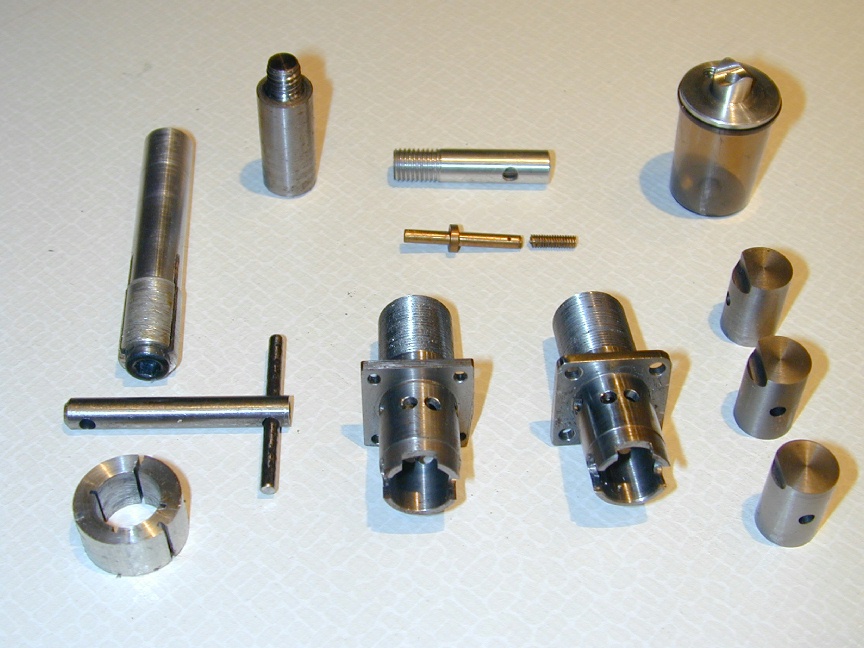
 Enter the expandable, split lap. I first saw this one in an article by Roger Schroeder on building the Deezil compression ignition engine. Roger's lap is on the left of this photo (of tools and snafu's). After turning parallel for a length of about half the bore length to be finished, the lap is necked down, drilled, tapped and taper bored a short distance for a cap-head screw whose head carries a matching taper. The lap is then split quadrilaterally up into the 'necked-down" area so that as the screw is inserted, the lap petals are forced into a light cone whose apex will actually be somewhere out in space, far beyond the end of the chucking piece. This design gives us the adjustable capability required and imparts a slight taper to the bore. If we lap with the top of the cylinder towards the chucking piece, we'll have liners with that oh so necessary "pinch" about TDC to give lovely compression, but that become progressively loose towards BDC. This lowers friction where a tight compression seal is less of a requirement (we still want to develop "primary" compression in the crankcase, but the pressure is comparatively low). Roger's lap—which he's been using for years before the AHC article in SIC—accomplished this very effectively. The only downside is that while one screw may expand multiple laps, each lap needs a tapered cavity in the end that has to be cut with reasonable accuracy.
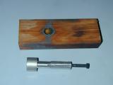 In his instructions for making the Mate, David Owen came up with a similar design that does not require any taper cutting. As seen in this shot from the AHC project, the split-petal design remains unchanged, as does a tapped hole (done before splitting, obviously). The difference however is that the thread is cut with a #2 tap, resulting in a short length of tapered thread. When the tip of a screw encounters this, the petals will open almost as before (note the "almost"). I liked this idea so much that it quickly became my standard process for cylinder lap manufacture.
 This exaggerated drawing shows what is going on and why it is important that the petal slits extend past the working surface; why the point where the taper cut by the #2 tap should not be too far down the body; and why the lap should be a close initial fit in the un-lapped bore. The first point should be obvious: the lap expands by bending. Bending implies a radius. We want the working area to be flat, so the bending needs to take place before the working lap surface. The angle rate at which the lap expands per turn of the screw depends on where the force is applied in relation to where the bending occurs. For fine adjustment, we want this to be as far away as possible while still retaining an adequate "start" for the thread. And finally, try to imagine what an undersize lap like the one drawn here would do as it is stroked back and forth in the bore. We are aiming to remove no more than 0.002" from the bore; perhaps less than 0.001". Given spring-back in the boring tool, the hole will most likely be lightly tapered already (which is why you should always bore from the bottom of the cylinder, never the top). Our lap is intended to regularize the circularity of the bore, finely finish the surface, and impart a taper in the vicinity of 0.0005" to 0.001" in diameter per inch, without creating "bell mouthed" ends.
As the lap is expanded, the screw becomes loose in its thread at the entry point. There is the possibility that pressure from the bore will try to close this gap, inducing a second bend in the tool, this time within the working area. I'd also noticed that this lack of support at the end made re-truing a lap (for a smaller bore) impossible on this style design, while it was practical on Roger's tapered screw type. So what is needed is something which combines the ease of manufacture of the second with the better support for the petals of the first. Duck soup, as they say, provided you have a duck, or in this case, a taper turning attachment.
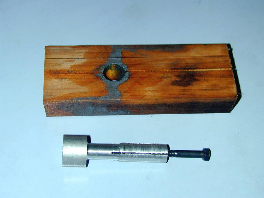
 What you are looking at here is a tapered 10-32 screw. It starts out with a diameter of 0.190" for the first quarter inch, than increases over the next inch to about 0.200", give or take. This means that one turn in of the screw will increase the diameter by approximately 0.0003". The end has been tapped for an 8-32 cap head screw and one has been glued in as a means of turning the tapered screw. The short parallel thread was formed by running a die up the tapered thread after screw cutting to the required depth. This was intended to provide a positive start into the tapped hole, but was probably unnecessary. Laps can now be made to the #2 design, except the hole can be finished off with a bottoming #3 tap, and it does not matter where the bottom is, provided it's deep enough to give adequate adjustment. The expanding force will be applied at the end of the lap, and there's a good chance that the lap will be supported internally by the tapered screw reducing secondary distortion. The screw will be re-usable over all laps, provided they are large enough to take the internal 10-32 hole. Finally, using this screw, I was able to re-size a worn out lap successfully. Only fly is you gotta have a taper turning capability. Mine came from a Hemingway kit and I heartily recommend it (see Suppliers Page).
Morton M5 from the Solid
 Some time ago, I was contacted by a gentleman who'd purchased a set of Morton M5 plans from eBay and was intending to make one, but rather than buy castings from Bruce Satra, he planned to machine all parts from the solid! Now this is a serious undertaking and not one to be contemplated by anyone who is not a professional machinist, very well versed (and equipped) in CAD/CAM machining centers. Fortunately that is exactly his qualification and after six months of serious work, the results are emerging from the cutter. They are, to say the least, astounding. For more pictures, visit the Engine Gallery.
Vernal's Morton M1 and M2 Kits
 While talking about Bruce Satra of Vernal Engineering, I received an email (not from Bruce, who is not on speaking terms with his computer), telling me that Vernal is about to offer a casting kit for a horizontally opposed twin based on Morton heads. Some time back, Bruce added a single based on a Morton cylinder to his catalogue (seen here as a picture of a picture). Called the "M1", this engine is derived from a design by Canadian builder Dennis Fadden whose M14 appeared here last month. The M1 kit includes all required castings, bearings, finished cam shaft and gears, plus required hardware. You supply the steel for the crankshafts. The M1 slightly simplified head construction by gluing in the valve cages with high temperature Locktite, rather than using the annular brass screws as designed by Glen Morton. Bruce also offers complete cylinder heads, compatible with original M5's, ready to bolt on and run. I imagine the M2 will effectively be two of these in "boxer" configuration with the crankshaft driven spur gear driving two camshaft gears, one of which would carry the distributer. The tricky part, assuming a simultaneous firing twin, will be the two throw crank and big-end arrangement. Pricing and availability of the M2 are unknown as yet, but I'll let 'yall know as soon as I find out more details. I also fear I will find this kit irresistible. At least the Ozzie dollar has been improving, exchange-wise, against the greenback lately—having just broken briefly through the 70 cent barrier for the first time since 1997!
Sky Angel 36
 I'll willingly confess to being partial to twin cylinder engines and to having a pronounced diesel fixation—not to mention the other fix arising from diesel fuel fumes. Generally speaking, ignition type singles don't do a lot for me, but isn't this a beauty? You are looking at a sneak-preview of a collaboration between Robert Palfrey, Roger Schroeder, and Tim Dannels. Bob has developed the engine and written a construction series for it. Tim will be publishing the series in Engine Collectors' Journal (see Suppliers Page and subscribe now!). Roger will be adding the casting kit, comprising case, backplate, and venturi to his Classic Model Engine kit list as soon as the series commences. In the mean time, drool over picture. Bob sent a lot of others as well and they have been added to the Engine Gallery.
Engine Of The Month: Yin-Yan diesels
 Why do we call these Yin-Yans? One side of the crankcase says "Silver Swallow", the other says "Made in China" (and there's pictograms above each that's probably the moral equivalent of the English). The box says "Silver Swallow". The charming Chinglish instructions ("This is engine we have made for you and is the engine you will use") call them "Silver Swallow". Yet everyone seems to refer to them as "Yin-Yans"! Beats the hell outa me, lieutenant. But read about them by clicking on the picture anyway.
Rear Rotor Madness
The development work on my adaptation of Bert Streigler's Red Rover AHC led to looking at a couple of commercial rear rotor arrangements—which in turn let to this diversion and page-filler. Below are some backplates for commercial, rear rotary valve engines and rear drum valve engines. Following my normal web page practice, you can click on a photo to see it in greater detail. See how many you can identify. Next month, I'll give the answers. There's no prize on offer, apart from the a whiff of smugness those scoring 100% will doubtless exude... .

Photo 1
|

Photo 2
|

Photo 3
|

Photo 4
|

Photo 5
|

Photo 6
|

Photo 7
|

Photo 8
|

Photo 9
|
 And for bonus points, identify the engine belonging to this rear drum backplate. Hint: it's from a limited production run engine (mine is serial number 119), made in Australian late in the last century and it was not manufactured by Gurdon Burford. Note that the two slots allow the venturi to be oriented on the same, or opposite side of the case as the cylinder.
Feeney Four-Stroke Kit
Last month, I reported that Art DeKalb is taking advance orders for a limited run of Feeney four-stroke kits. As the kits include custom made skew gears, Art needs to reach a critical minimum number of deposits to make the venture viable. [Vested Interest Warning] If the production run does not go ahead, deposits will be refunded, but I won't be able to buy the gear I need to complete my Feeney! So if you are thinking about making one of these someday, act now! This will be your last chance...
 Sydney Collecto
 Editorial
 Piston Material Choices


